
Illumination system

a technology of illumination system and illumination chamber, which is applied in the direction of lighting and heating apparatus, printed circuit aspects, electrical apparatus, etc., to achieve the effect of avoiding risks and improving installation conditions

Active Publication Date: 2018-07-19
ANTARES ILUMINACION SA
View PDF1 Cites 7 Cited by
  • Summary
  • Abstract
  • Description
  • Claims
  • Application Information

AI Technical Summary

Benefits of technology

The invention is a lighting system that makes it easier to install, reduces risks during operation, and doesn't modify the electrical properties of the system. The goal is to make it simple and safe.

Problems solved by technology

The above systems have the disadvantage that it is necessary to arrange the functional unit within a support profile which must then be introduced vertically into a support structure to carry out the coupling of the functional unit within the support structure.

Method used


Image

  • Illumination system
  • Illumination system
  • Illumination system

Examples


Embodiment Construction

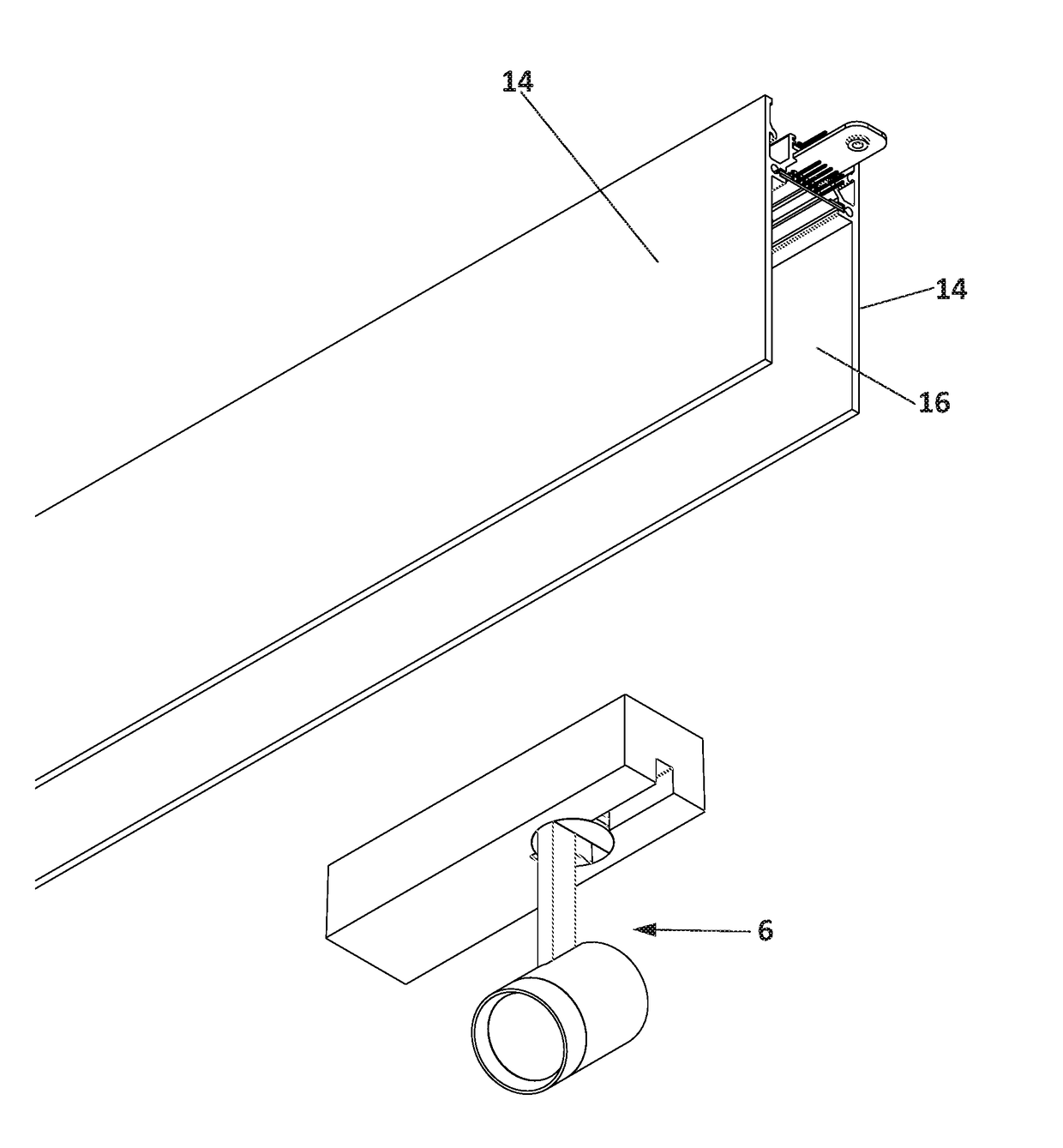
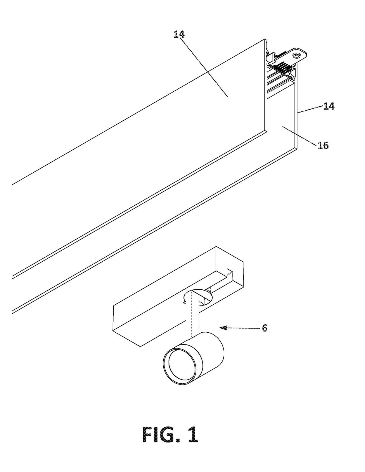
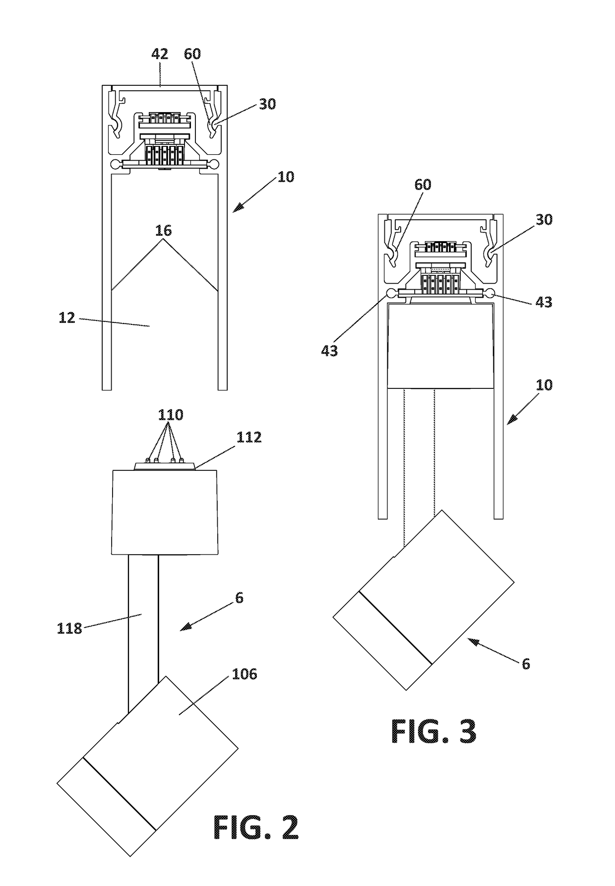
[0008]The present invention relates to a lighting system which can be coupled to the ceiling, wall or floor of a room in which it is arranged.

[0009]The lighting system comprises a lighting device which is movable from a position where all or part is housed inside a support structure to a position in which it is partly housed in or it totally protrudes from the support structure respectively.

[0010]The lighting system comprises:[0011]A support structure extending in a longitudinal direction and forming an internal space;[0012]At least one functional unit extending in a longitudinal direction which can be accommodated in the internal space of the support structure, provided with a lower surface comprising electrical contacts;[0013]At least one lighting device provided with lighting means and comprising electrical contacts which can be coupled to the electrical contacts of the functional unit to maintain the lighting device connected to the functional unit, wherein the lower surface of ...


PUM


Abstract

The present invention relates to a lighting system that enhances installation conditions, avoiding risks therein and during operation of the system over time, and which facilitates insertion of the electrical contacts of the functional unit and allows its concealment without modifying the conductive properties thereof.

Description

OBJECT OF THE INVENTION[0001]The present invention relates to a lighting system that enhances installation conditions, avoiding risks therein and during operation of the system over time.[0002]The object of the present invention is a lighting system that facilitates the insertion of the electrical contacts of the functional unit and allows its concealment without modifying the conductive properties thereof.BACKGROUND OF THE INVENTION[0003]The prior art discloses lighting systems that allow carrying out the integration of lighting devices in hollows inside walls, ceilings or floors.[0004]These systems comprise a support structure extending in a longitudinal direction and forming an internal space accessible from an opening, at least one functional unit capable of being housed in the internal space of the support structure, provided with a lower surface in which electrical contacts are embodied and at least one lighting device provided with lighting means and comprising electrical con...

Claims


Application Information

Patent Timeline
Patent Type & Authority Applications(United States)
IPC IPC(8): F21V23/06F21V21/35F21V17/10F21V23/00F21V21/088H05B33/08H05B44/00
CPCF21V23/06F21V21/35F21V17/105F21V23/001F21V21/088H05B33/0845F21Y2115/10F21S8/022F21S8/026F21V19/004H05K3/246F21Y2101/00H05K2201/0323F21S4/28F21Y2103/10H05B45/10F21S8/038F21S8/066F21V21/005
Inventor MARTINEZ WEBER, FEDERICO
Owner ANTARES ILUMINACION SA
Learn More