

Energy harvesting systems for providing autonomous electrical power to mobile devices
a technology of energy harvesting and mobile devices, applied in the direction of photovoltaic supports, greenhouse gas reduction, other domestic objects, etc., can solve the problems of degrading the operation of the layer, affecting the aesthetics of the structure, and significantly reducing the efficiency of the layer, so as to achieve the effect of “tricking” the human eye and superior light transmission
- Summary
- Abstract
- Description
- Claims
- Application Information
AI Technical Summary
Benefits of technology
Problems solved by technology
Method used
Image

Examples
Embodiment Construction
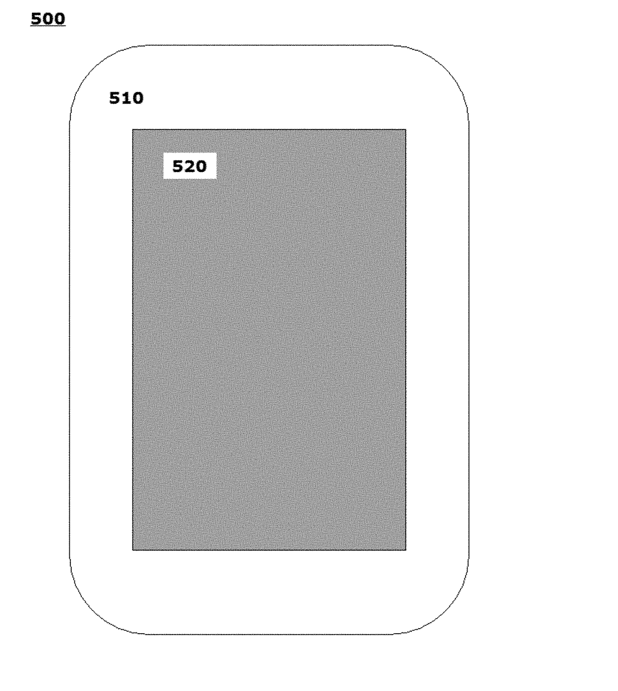
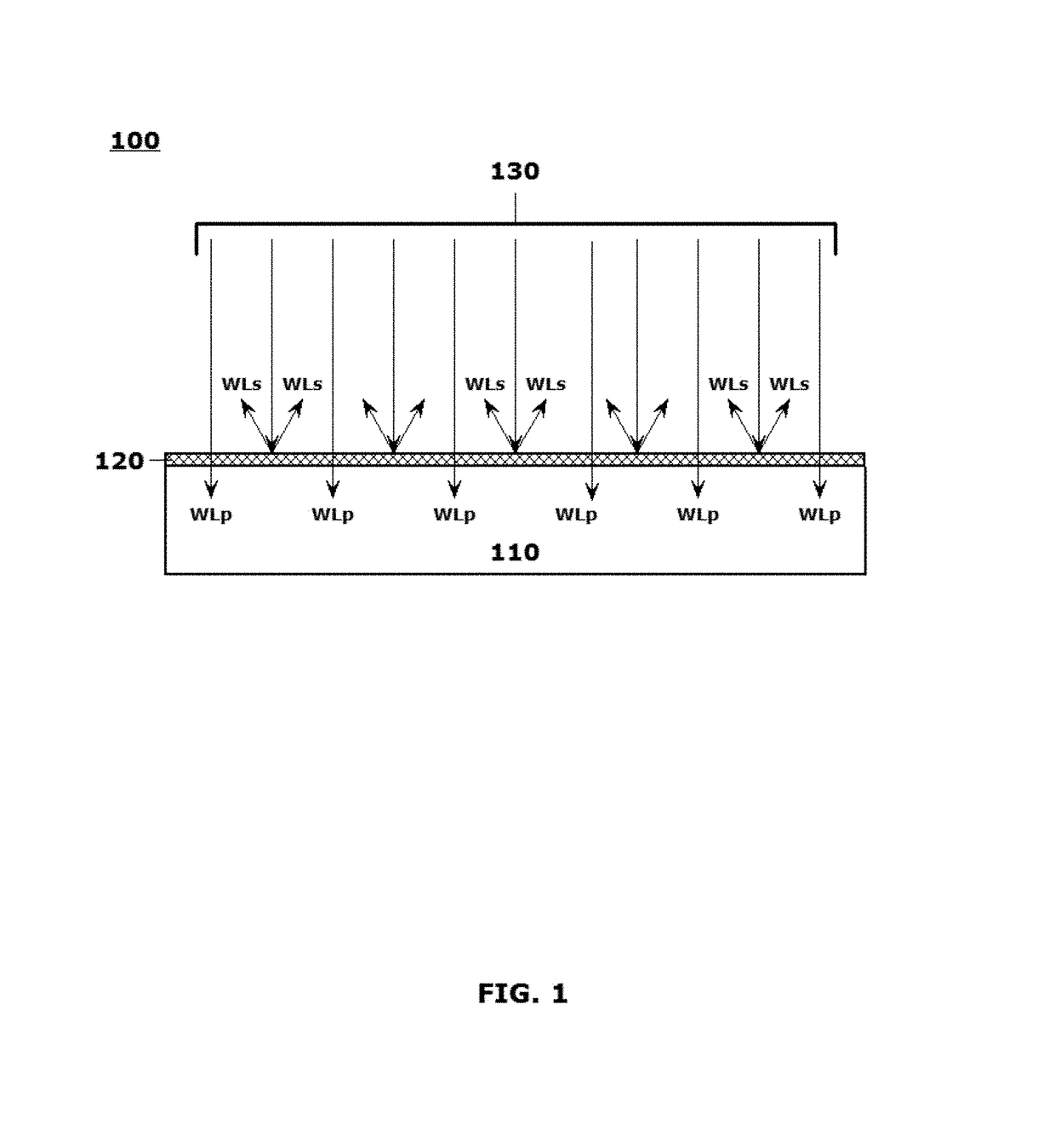
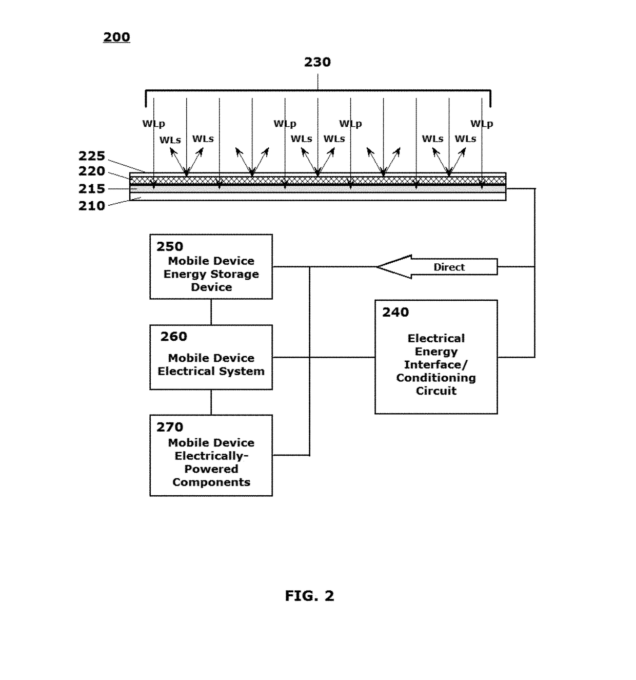
[0002]This disclosure is directed to a unique set of structural features on an outer surface of a mobile device, or a mobile device case, the structural features combining to implement an aesthetically neutral, or aesthetically pleasing, energy harvesting system that provides autonomous electrical power to a mobile device on which the system is installed, and / or to individually electrically-powered components in the mobile device. Color-matched, image-matched and / or texture-matched optical layers, which provide an essentially same appearance from any viewing angle, and provide superior light transmission across the range of light impingement angles, are formed over energy harvesting components, including photovoltaic components.
2. Related Art
[0003]U.S. patent application Ser. No. 15 / 006,143 (the 143 application), entitled “Systems and Methods for Producing Laminates, Layers and Coatings Including Elements for Scattering and Passing Selective Wavelengths of Electromagnetic Energy,” a...
PUM
| Property | Measurement | Unit |
|---|---|---|
| diameter | aaaaa | aaaaa |
| diameter | aaaaa | aaaaa |
| diameters | aaaaa | aaaaa |
Abstract
Description
Claims
Application Information