
Energy harvesting methods for providing autonomous electrical power to vehicles and electrically-powered devices in vehicles

a technology of energy harvesting and electrical power, applied in the direction of light to electrical conversion, doors, transportation and packaging, etc., can solve the problems of degrading the operation of layers, affecting the aesthetics of the structure, and significantly less efficient layers, so as to achieve the effect of “tricking” the human eye and superior light transmission

Active Publication Date: 2022-06-07
FACE INT
View PDF12 Cites 0 Cited by
  • Summary
  • Abstract
  • Description
  • Claims
  • Application Information

AI Technical Summary

Benefits of technology

The patent text describes systems and methods for creating energy transmissive overlayers that can hide photoelectric devices. These overlayers use special techniques to allow light to pass through while still appearing opaque. The technique involves matching the refractive indices of suspended particles with those of the matrix material in which they are suspended. The patent also discusses the use of these overlayers in vehicles to improve battery-powered electric vehicles, reduce reliance on charging infrastructure, and increase the useful lifespan of batteries. The patent also mentions the use of these overlayers on photovoltaic arrays to provide an opaque surface that still allows light to pass through.

Problems solved by technology

Significant drawbacks to wider proliferation of photocells used in a number of potentially beneficial operating or employment scenarios are that the installations, in many instances, unacceptably adversely affect the aesthetics of the structure, object or host substrate surface on which the PV layers are mounted for use.
PV layers typically must be generally visible, and the visual appearance of the PV layers themselves cannot be significantly altered from the comparatively dark greyscale to black presentations provided by the facial surfaces without rendering the layers significantly less efficient, substantially degrading their operation.
Presence of photocells and PV layers in most installations is, therefore, easily visually distinguishable, often in an unacceptably distracting, or appearance degrading, manner.
PV layer installations are often shunned as unacceptable visual detractors or distractors adversely affecting the appearance or ornamental design of the structures, objects or products.
The original electric passenger vehicles had very limited range based predominantly on limited battery size and first-generation efficiency in those batteries.
A challenge remains with respect to extending usable ranges for the electric vehicles even further.
This challenge is particularly acute in areas in which infrastructure development, particularly with respect to the emplacement, and identification of locations, of electric vehicle charging stations have failed to keep pace with the commercialization of the electric vehicles themselves.
The comparatively limited ranges of electric vehicles, and the limited accessibility to remote charging stations, has limited advancement in the field of electric vehicles based in part on a phenomenon commonly referred to as “range anxiety.” Concern over limiting one's driving habits based on an ability to access a known power source to recharge the electric vehicle has tended to serve as a detractor to broader commercialization of electric vehicle technology.
Separately in virtually all vehicles, a power drain on the installed electrical generation and storage systems in vehicles has increased rapidly and substantially.

Method used


Image

  • Energy harvesting methods for providing autonomous electrical power to vehicles and electrically-powered devices in vehicles
  • Energy harvesting methods for providing autonomous electrical power to vehicles and electrically-powered devices in vehicles
  • Energy harvesting methods for providing autonomous electrical power to vehicles and electrically-powered devices in vehicles

Examples


Embodiment Construction

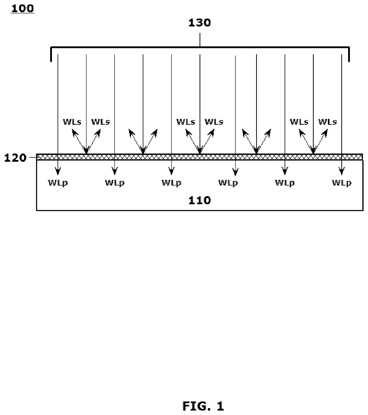
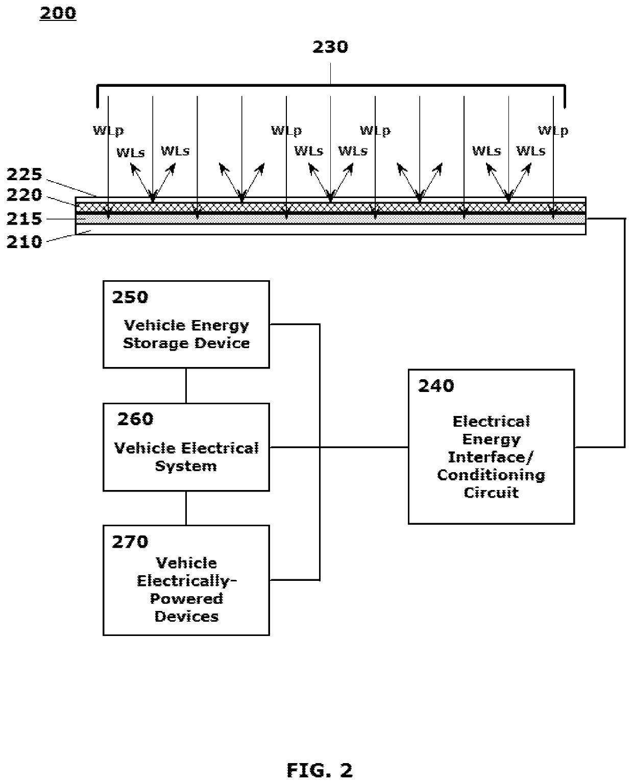
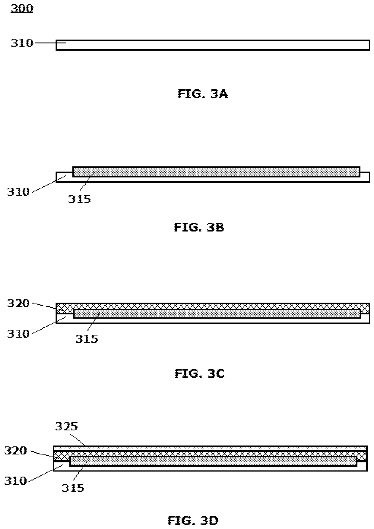
[0002]This disclosure is directed to a unique method for forming a set of structural features on an outer surface of a body structure of a vehicle, the structural features combining to implement an aesthetically neutral, or aesthetically pleasing, energy harvesting system that provides autonomous electrical power to vehicles on which the system is installed, and / or to electrically-powered devices in those vehicles. Color-matched, image-matched and / or texture-matched optical layers, which provide an essentially same appearance from any viewing angle, and provide superior light transmission across the range of light impingement angles, are formed over energy harvesting components, including photovoltaic components.

Related Art

[0003]U.S. patent application Ser. No. 15 / 006,143 (the 143 application), which published as U.S. Patent Application Publication US 2016-0306078 A1 on Oct. 20, 2016, entitled “Systems and Methods for Producing Laminates, Layers and Coatings Including Elements for S...


PUM


Abstract

A method is provided that integrates an autonomous energy harvesting capacity in vehicles in an aesthetically neutral manner. A unique set of structural features combine to implement a hidden energy harvesting system on a surface of the vehicle to provide electrical power to the vehicle, and / or to electrically-powered devices in the vehicle. Color-matched, image-matched and / or texture-matched optical layers are formed over energy harvesting components, including photovoltaic energy collecting components. Optical layers are tuned to scatter selectable wavelengths of electromagnetic energy back in an incident direction while allowing remaining wavelengths of electromagnetic energy to pass through the layers to the energy collecting components below. The layers uniquely implement optical light scattering techniques to make the layers appear opaque when observed from a light incident side, while allowing at least 50%, and as much as 80+%, of the energy impinging on the energy or incident side to pass through the layer.

Description

[0001]This non-provisional application for patent is a continuation of U.S. patent application Ser. No. 15 / 416,259, filed in the United States Patent and Trademark Office (USPTO) on Jan. 26, 2017, titled “ENERGY HARVESTING METHODS FOR PROVIDING AUTONOMOUS ELECTRICAL POWER TO VEHICLES AND ELECTRICALLY-POWERED DEVICES IN VEHICLES”, which issued from the USPTO as U.S. Pat. No. 10,347,777 on Jul. 9, 2019, which is incorporated herein by reference in its entirety; this application is also a continuation-in-part (CIP) of U.S. patent application Ser. No. 15 / 416,234, entitled “Energy Harvesting Systems For Providing Autonomous Electrical Power To Vehicles And Electrically-Powered Devices In Vehicles,” which was filed in the USPTO on Jan. 26, 2017 and which published as U.S. Patent Application Publication U.S. 2018-0212078 A1 on Jul. 26, 2018, the disclosure of which is hereby incorporated by reference herein in its entirety.BACKGROUNDField of the Disclosed Embodiments[0002]This disclosure i...

Claims


Application Information

Patent Timeline
Patent Type & Authority Patents(United States)
IPC IPC(8): H01L31/0232H01L31/02B62D25/12B60L8/00H02S99/00H01L31/0236H02S40/34B60J5/04H01L31/0203B62D25/06H02S40/22H01L31/048H01L31/0392H01L31/0216B62D33/02
CPCH01L31/02327B60J5/04B60L8/003B62D25/06B62D25/12B62D33/02H01L31/02H01L31/0203H01L31/0236H01L31/02168H01L31/0392H01L31/048H02S40/22H02S40/34H02S99/00Y02T10/7072H02S20/30
Inventor BOYD, CLARK D.FACE, BRADBURY RSHEPARD, JEFFREY D
Owner FACE INT
Learn More