
Methods for making compositions of materials for forming coatings and layered structures including elements for scattering and passing selectively tunable wavelengths of electromagnetic energy

a technology of electromagnetic energy and compositions, applied in the direction of diffusing elements, anti-reflective coatings, instruments, etc., can solve the problems of limiting the ability to see, adversely affecting the light transmissive properties of ambient light incident to the lighted side of the mirror or tinted window, and generally no way to modify the unfortunate aesthetic drawbacks presented by typical pv cell installations. , to achieve the effect of “tricking” the human body, greater latitud

Active Publication Date: 2021-05-18
FACE INT
View PDF12 Cites 0 Cited by
  • Summary
  • Abstract
  • Description
  • Claims
  • Application Information

AI Technical Summary

Benefits of technology

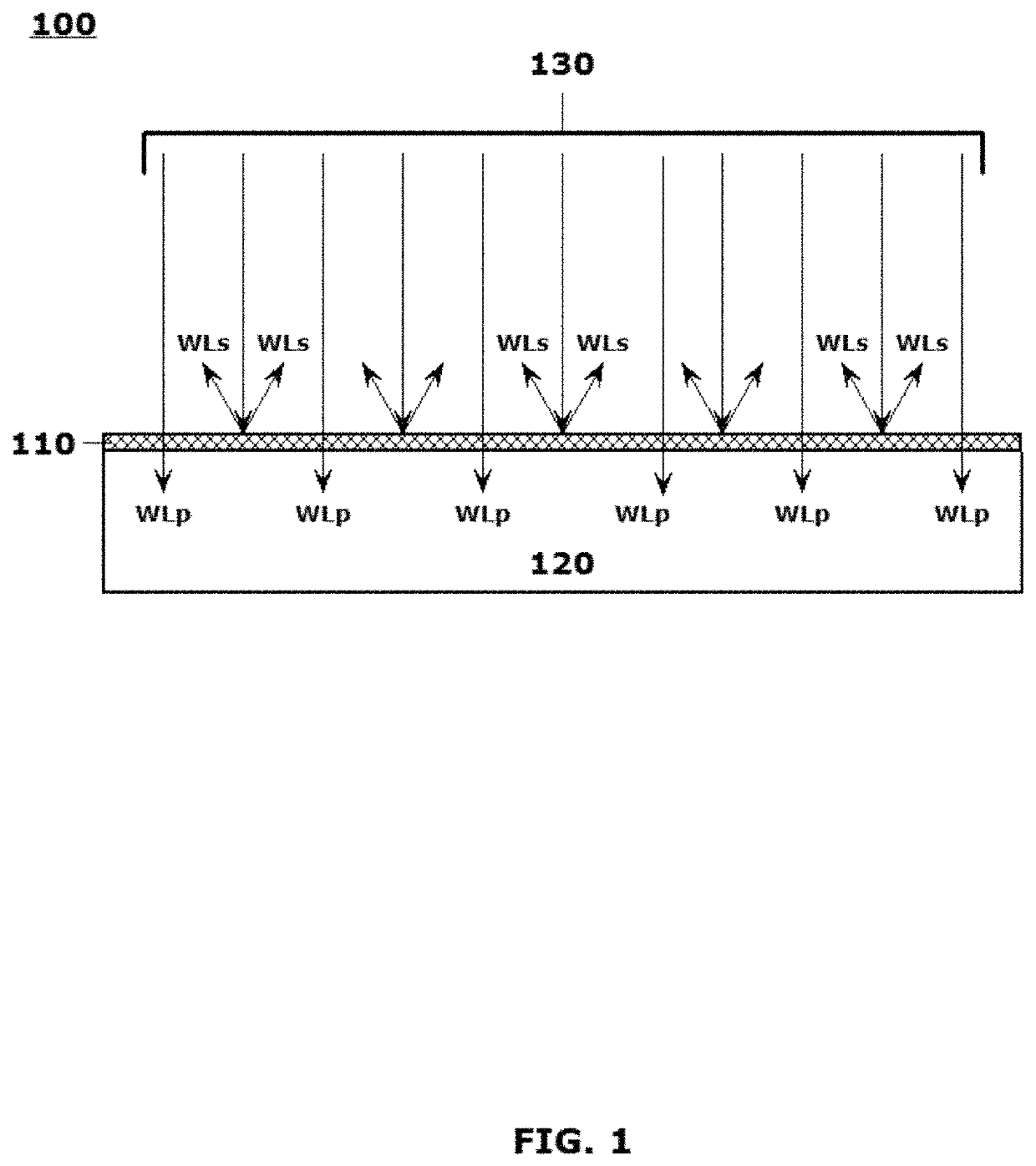
[0007]The 143 and 145 applications introduce systems and methods that provide particularly formulated energy or light transmissive overlayers. These overlayers, generally in the form of surface treatments and / or coverings, are formulated to support unique energy transmission and light refraction schemes to effectively “trick” the human eye into seeing a generally opaque presentation of the surface when observed from a light incident side. These overlayers are formulated to support transmission of visual light, or near-visual light, in a manner that allows a substantial percentage of the electromagnetic energy to penetrate the surface treatments and coverings in a comparatively unfiltered manner. Although particularly advantageously employed to support displayed visual optical effects, the principles according to this disclosure may be equally applicable to filtering wavelengths of electromagnetic energy lying outside the visual spectrum. The material compositions disclosed in the 143 and 145 applications, while important, and useful in many operational employment scenarios, are constrained in the manner in which the disclosed layers can be applied. Improvements on the layer compositions disclosed in those applications may provide greater latitude in the manufacturing processes by which objects including the disclosed particularized layers may be formed.
[0009]The energy transmissive layers disclosed in the 143 and 145 applications rely on a particular cooperation between refractive indices of the disclosed micron-sized particles or spheres with cooperating refractive indices of the matrix materials in which those micron-sized particles are suspended for deposition on prepared surfaces. This coincident requirement between the refractive indices of the matrix material and the refractive indices of the suspended particles limits deposition of these material suspensions of particles on substrates to techniques in which the deposition of the materials can be carefully controlled.
[0010]It would be advantageous to develop techniques by which to form suspended micron-sized particles in a manner that controls the refractive indices of the developed layers regardless of a delivery method by which the suspensions of micron-sized particles are deposited onto a broad spectrum of substrate surfaces.
[0013]Exemplary embodiments may dispose a substantially clear outer layer on the multi-layered structure of the substantially transparent micron-sized particles in a manner that assures that particle-to-particle refraction interference is minimized.
[0017]Exemplary embodiments may form individual energy scattering layers out of substantially-transparent micron-sized particles, including nanoparticles, which may be particularly overcoated in substantially energy-neutral layers that control a minimum spacing of the coloration layers of the particles so as to substantially eliminate micro- and / or nano-voids between the particles and yet control spacing of the coloration components of the particles so as to reduce particle-to-particle refractive interference.
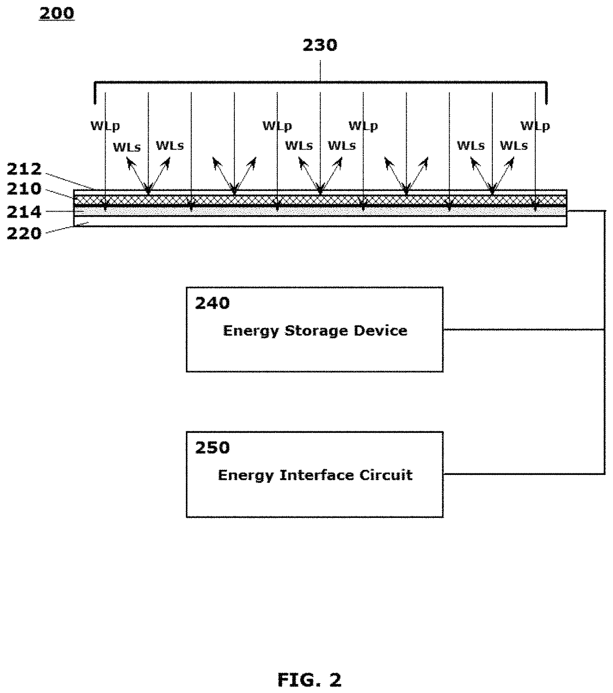
[0023]In embodiments, an appearance of a photocell array, or a thin-film PV layer, may be enhanced by overcoating with a protective layer or film that is particularly arranged to allow an appearance of the photocell array, or thin-film PV layer, to be masked behind the protective layer or film thereby outwardly presenting one or more of a wide range of chosen colors and / or chosen patterns in a manner that does not substantially disrupt or degrade an efficient operation of the photocell array, or thin-film PV layer.

Problems solved by technology

The modifications to the formerly transparent structures may limit an ability to see through a particular window or skylight to address privacy, security and / or other related concerns.
Thus, the principle of operation is to keep one side brightly lit rendering that side “difficult” to see through based on the principle that the reflected light masks visual penetration of the mirror from the brightly lit side.
The coatings or embedded layers, which are applied to, or included in, the mirror or window panels, ensure that a substantial portion of the incident light is reflected back from the “lighted” side of the mirror or tinted window, adversely affect the light transmissive properties of the ambient light incident to the lighted side of the mirror or tinted window as it passes through the panel.
Any such protective outer surface layers may provide some protection against adverse environmental effects and / or damage to facial surfaces of the PV layers, which tend to be comparatively fragile, but they provide generally no manner by which to modify the unfortunate aesthetic drawbacks presented by typical PV cell installations.
The 143 and 145 applications note that significant drawbacks to wider proliferation of photocells used in a number of potentially beneficial operating or employment scenarios are that such “required” installations, in many instances, adversely affect the aesthetics of the structure, object or host substrate surface on which the PV layers are mounted for use.
It is further known that the visual appearance of the PV layers cannot be significantly altered from the comparatively dark greyscale to black presentations provided by the facial surfaces without rendering the photocells significantly less efficient, substantially degrading their operation.
Presence of photocells and PV layers in most installations is, therefore, easily visually distinguishable, often in an aesthetically distracting or degrading manner.
As such, photocell and other PV layer installations often become unacceptable visual detractors or distractors adversely affecting the appearance or ornamental design of the structures, objects or products on which the layers may be otherwise advantageously applied and employed.

Method used


Image

  • Methods for making compositions of materials for forming coatings and layered structures including elements for scattering and passing selectively tunable wavelengths of electromagnetic energy
  • Methods for making compositions of materials for forming coatings and layered structures including elements for scattering and passing selectively tunable wavelengths of electromagnetic energy
  • Methods for making compositions of materials for forming coatings and layered structures including elements for scattering and passing selectively tunable wavelengths of electromagnetic energy

Examples


Embodiment Construction

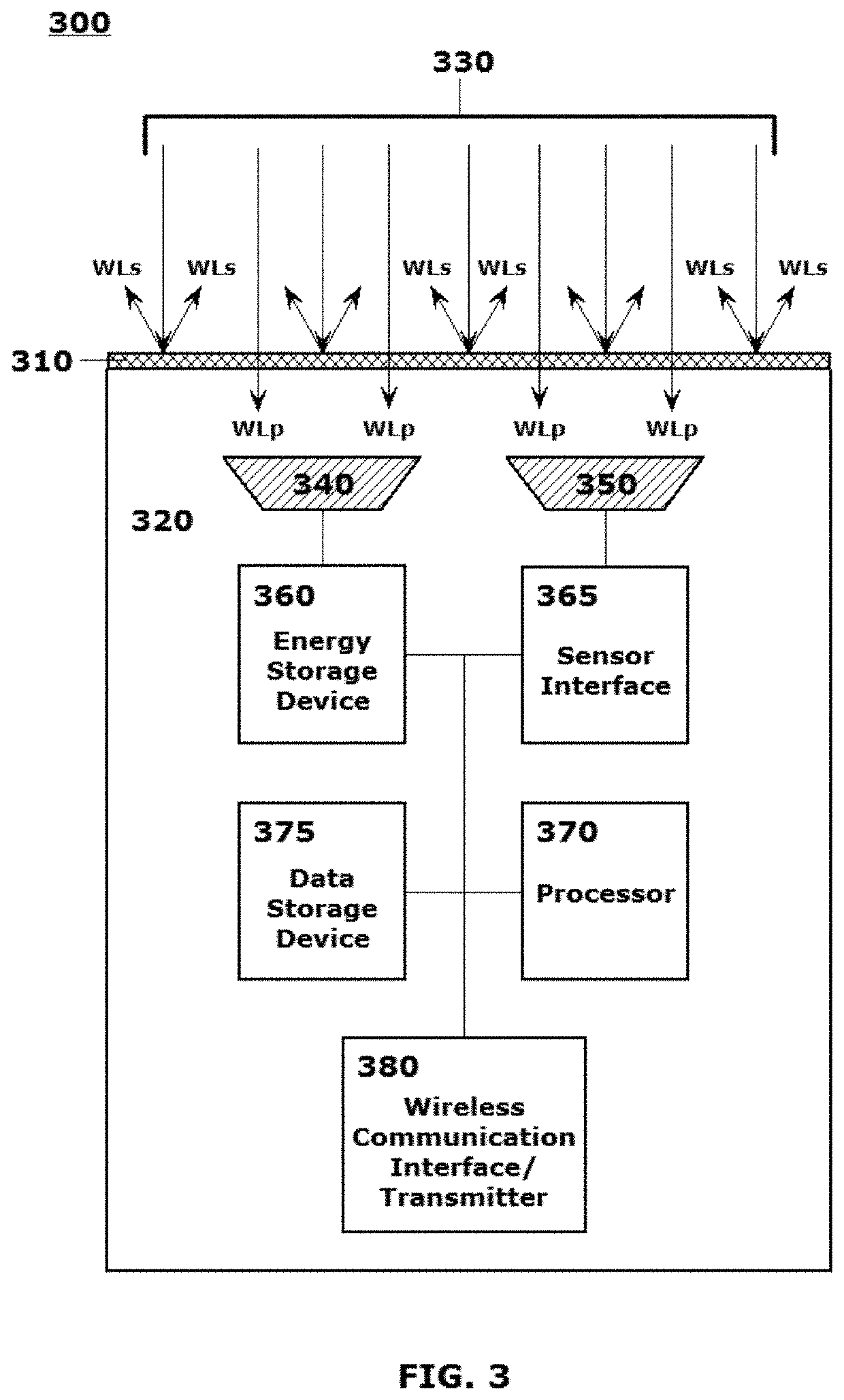
[0002]This disclosure describes forming a particular multi-layer micron-sized particle that is substantially transparent, yet that exhibits selectable coloration based on the physical properties of the particle layers manipulated in the forming process, resulting in the particles exhibiting controllable refractive indices. Also, material suspensions are provided for the particles to render them deliverable to form unique electromagnetic energy transmissive layers on substrates. These disclosed layers, once formed, selectively scatter specific wavelengths of electromagnetic energy back in an incident direction while allowing remaining wavelengths to pass therethrough, including uniquely implementing optical light scattering techniques in such energy (or light) transmissive layers to make those layers appear selectively opaque when observed from a light incident side, while allowing at least 50%, and as much as 80+%, of the energy impinging on the light incident side to pass through t...


PUM

PropertyMeasurementUnit
particle sizeaaaaaaaaaa
thicknessaaaaaaaaaa

Abstract

Methods are provided for forming a particular multi-layer micron-sized particle that is substantially transparent, yet that exhibits selectable coloration based on its physical properties. The disclosed physical properties of the particle are controllably selectable refractive indices to provide an opaque-appearing energy transmissive material when pluralities of the particles are suspended in a substantially transparent matrix material. Multiply-layered (up to 30+ constituent layers) particles result in an overall particle diameter of less than 5 microns. The material suspensions render the particles deliverable as aspirated or aerosol compositions onto substrates to form layers that selectively scatter specific wavelengths of electromagnetic energy while allowing remaining wavelengths of the incident energy to pass. The disclosed particles and material compositions uniquely implement optical light scattering techniques in energy (or light) transmissive layers that appear selectively opaque, while allowing 80+% of the energy impinging on the light incident side to pass through the layers.

Description

BACKGROUND[0001]This application is related to U.S. patent application Ser. No. 15 / 415,851, which published as USPTO pre-grant publication number US2018-0210121 A1 on Jul. 26, 2018, and issued as U.S. Pat. No. 10,247,861 on Apr. 2, 2019 entitled “Compositions of Materials for Forming Coatings and Layered Structures Including Elements for Scattering and Passing Selectively Tunable Wavelengths of Electromagnetic Energy,”; and U.S. patent application Ser. No. 15 / 415,864, which published as USPTO pre-grant publication number US 2018-0210119 A1 on Jul. 26, 2018 entitled “Delivery Systems and Methods For Compositions of Materials For Forming Coatings And Layered Structures Including Elements For Scattering and Passing Selectively Tunable Wavelengths Of Electromagnetic Energy,”; each of which was filed in the USPTO on Jan. 25, 2017, the disclosures of each of which are hereby incorporated by reference herein in their entirety.1. Field of the Disclosed Embodiments[0002]This disclosure descr...

Claims


Application Information

Patent Timeline
Patent Type & Authority Patents(United States)
IPC IPC(8): G02B5/02B05D5/06C23C16/455C08K9/10G02B5/28C09D5/00B05D1/02
CPCG02B5/0294C08K9/10C09D5/006C23C16/45525G02B5/0226G02B5/0278G02B5/285B05D1/02B05D5/065
Inventor BOYD, CLARK DFACE, BRADBURY RSHEPARD, JEFFREY D
Owner FACE INT
Learn More