Power assist module for coverings for architectural structures

a technology for architectural structures and power assist modules, applied in mechanical equipment, vibration suppression adjustments, door/window protective devices, etc., can solve problems such as wear and/or durability of modules, and achieve the effect of enhancing threaded engagement and preventing thread wear

Active Publication Date: 2018-08-02
HUNTER DOUGLAS INC
View PDF4 Cites 17 Cited by
  • Summary
  • Abstract
  • Description
  • Claims
  • Application Information

AI Technical Summary

Benefits of technology

[0009]Further, in one embodiment, the power assist module may also include a separate threaded insert configured to be received within the follower member. In such an embodiment, the threaded insert may be configured to threadably engage the threaded shaft member to allow the follower member to be rotationally coupled to the threaded shaft member. Additionally, the threaded insert may, in one embodiment, be formed from a dissimilar type of material than the threaded shaft member, with the differing materials being selected to prevent thread wear and / or to enhance the threaded engagement provided at the threaded interface defined between the threaded insert and the threaded shaft member.

Problems solved by technology

For example, due to the configuration and / or material properties of several of the components of the power assist modules, such modules may be subject to wear and / or durability issues, particularly with reference to the mechanical stops utilized within the power assist modules and at the locations of the threaded engagement defined between corresponding threaded components of the power assist modules.

Method used


Image

  • Power assist module for coverings for architectural structures
  • Power assist module for coverings for architectural structures
  • Power assist module for coverings for architectural structures

Examples


Embodiment Construction

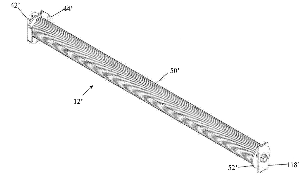
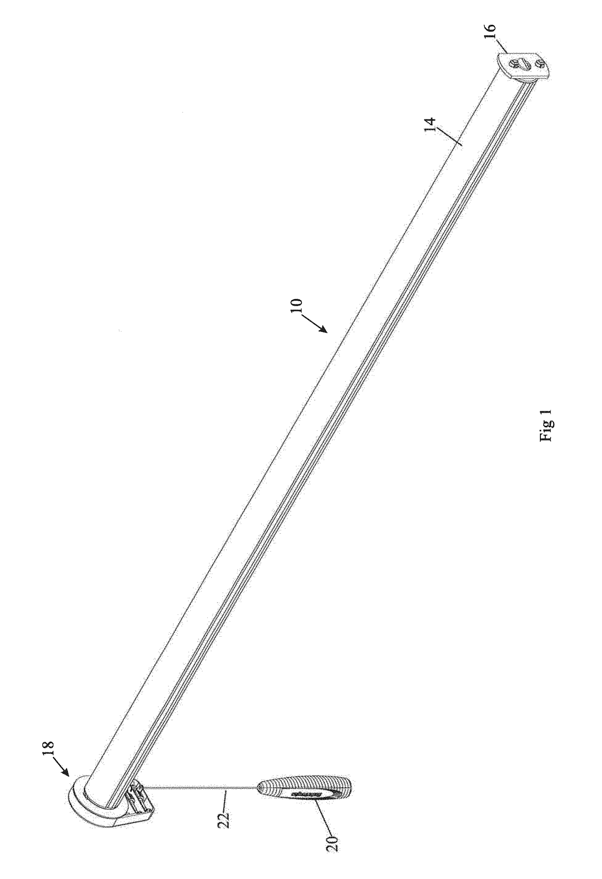
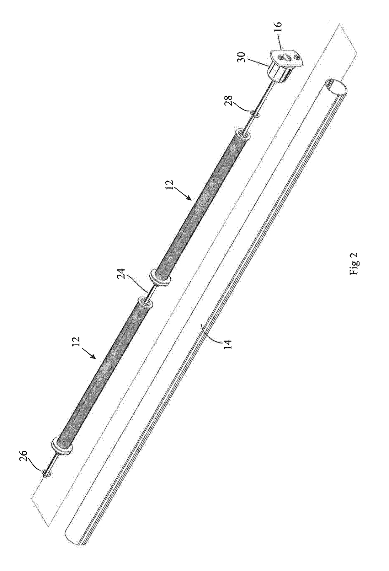
[0085]In general, the present subject matter is directed to a power assist module for a covering for an architectural feature or structure (referred to herein simply as architectural “structure” for the sake of convenience without intent to limit), such as a window or door. In several embodiments, the power assist module may be configured to assist the covering in moving from an extended position to a retracted position. For instance, in one embodiment, the power assist module may include a spring configured to be wound up as the covering is moved towards the extended position, thereby allowing the spring to store energy. Thereafter, the spring may be allowed to unwind or release its stored energy when it is desired to move the covering to the retracted position, thereby allowing the spring to assist in raising the covering.

[0086]In one embodiment, the power assist module may also include an elongated spring shaft configured to be received within the spring such that the spring surr...


PUM


Abstract

In one aspect, a power assist module for covering for an architectural structure may include a spring and a spring shaft extending through the spring. Additionally, the power assist module may include a threaded shaft member coupled to the spring shaft and a follower member rotationally coupled to the threaded shaft member such that the follower member is moved axially along the threaded shaft member as the follower member is rotated relative to the threaded shaft member.

Description

FIELD OF THE INVENTION[0001]The present subject matter relates generally to coverings for architectural structures and, more particularly, to a power assist module for a covering with improved wear resistance, increased durability, and enhanced performance.BACKGROUND OF THE INVENTION[0002]In a top down roller shade, the entire light blocking material typically wraps around a rotator rail (also referred to as a rotator tube or roller tube) as the shade is raised or retracted. Therefore, the weight of the shade is transferred to the rotator rail as the shade is raised, and the force required to raise the shade is thus progressively lower as the shade (the light blocking element) approaches the fully raised (fully open or retracted) position. Of course, there are also bottom up shades and composite shades which are able to do both, to go top down and / or bottom up. In the case of a bottom / up shade, the weight of the shade is transferred to the rotator rail as the shade is lowered, mimic...

Claims


Application Information

Patent Timeline
Patent Type & Authority Applications(United States)
IPC IPC(8): E06B9/60E06B9/62E06B9/68E06B9/78
CPCE06B9/60E06B9/62E06B2009/785E06B9/78E06B2009/583E06B9/68E06B9/42E06B9/50E06B9/84E06B9/90
Inventor FISHER, ROBERT E.
Owner HUNTER DOUGLAS INC
Why Eureka
Try Eureka