Pneumatic control ring

a technology of pneumatic control and control ring, which is applied in the direction of filament handling, continuous wounding machines, textiles and papermaking, etc., can solve the problems of thread wear, slowing down spindle speed, current control ring for twisting and continuous spinning frames, etc., to prevent thread wear and facilitate higher processing speed.

Inactive Publication Date: 2003-06-10
GALAN INT
View PDF2 Cites 0 Cited by
  • Summary
  • Abstract
  • Description
  • Claims
  • Application Information

AI Technical Summary

Benefits of technology

The object of this invention, as shown by its title, is related to a pneumatic control ring with application in ring twisting machines, continuous spinning frames and double twisting frames, which, by creating an air cushion between the ring and the thread, and lubricating the contact area between them, avoids the balloon effect and prevents the thread from wearing down due to friction against the surface of the control ring of the balloon, facilitating higher processing speeds.

Problems solved by technology

The current control rings for twisting and continuous spinning frames have a problem when carrying out high speed and / or delicate thread twisting due to the balloon effect.
This problem causes the thread to wear down by friction against a surface which is the balloon control ring so it cannot be processed in this way, the solution being, consequentially, increasing tension to reduce the balloon so that it does not rub against the control ring, and slowing down the spindle speed.

Method used


Image

  • Pneumatic control ring
  • Pneumatic control ring

Examples


Embodiment Construction

The pneumatic control ring has been developed to avoid the aforementioned inconveniences that occur with twisting machines and continuous spinning frames.

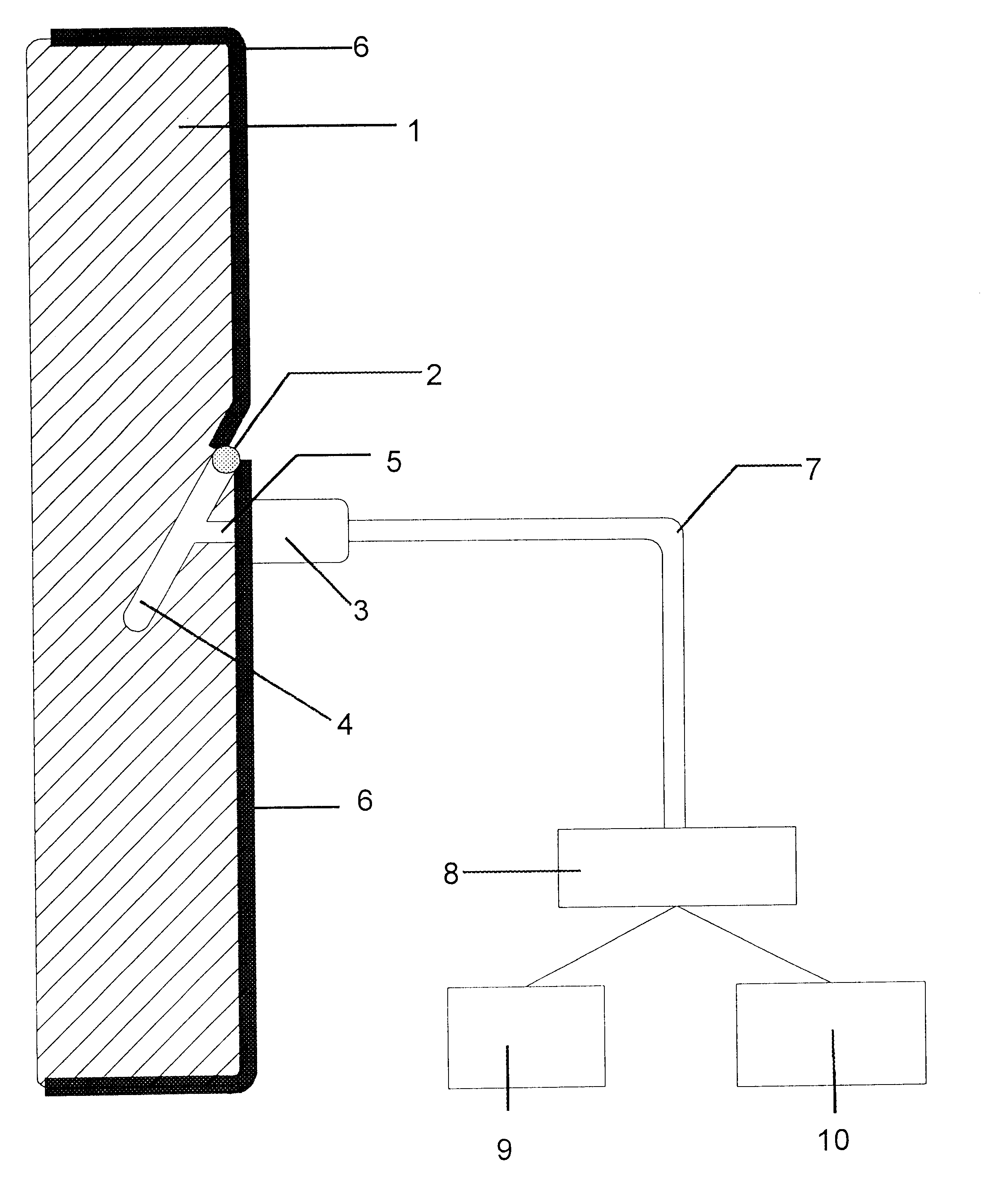
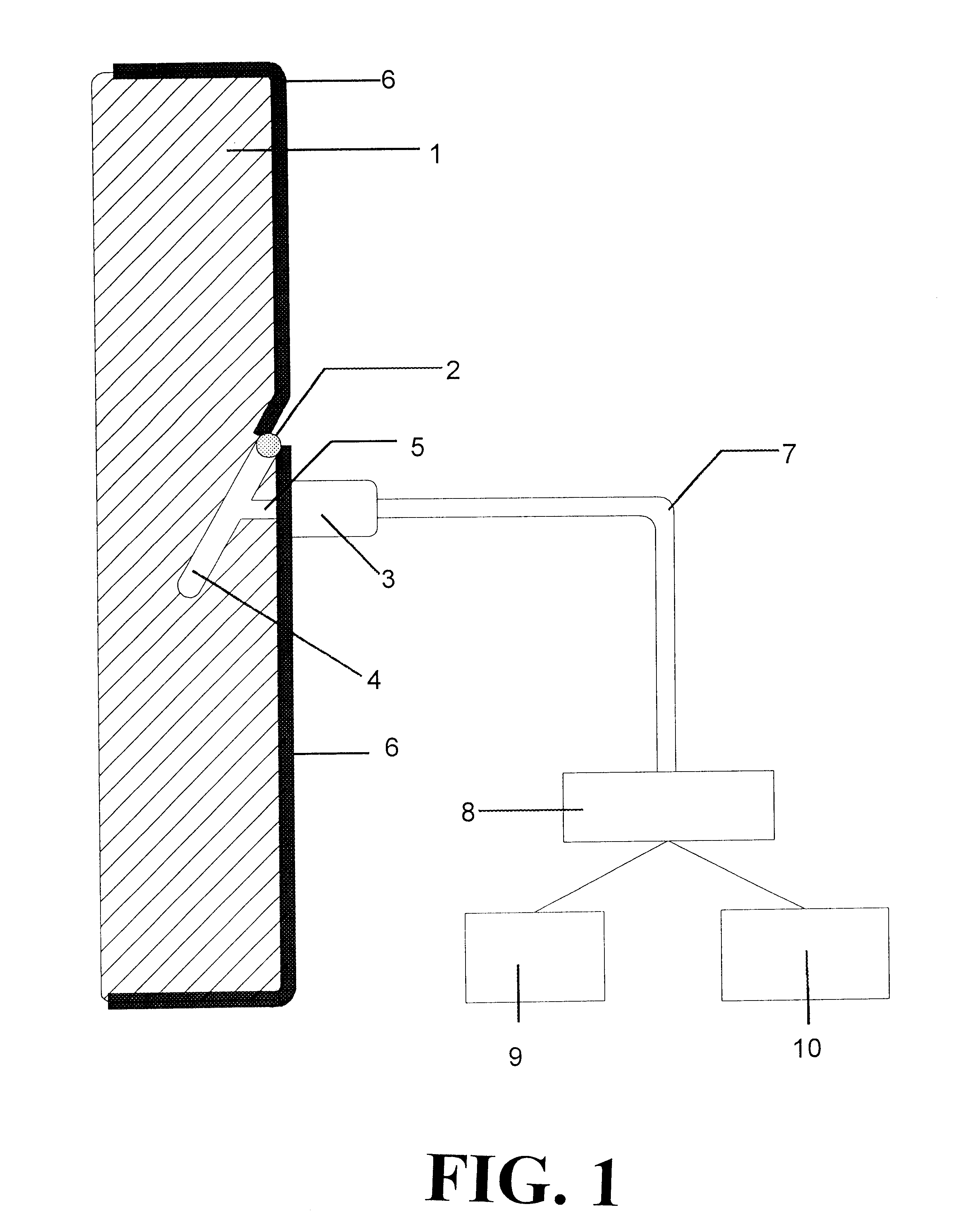
The pneumatic control ring consists of a hollow, cylindrical-shaped ring made of sintered material, which is lubricated with a mixture of compressed air and lubricant from an external mixer, which in turn creates an "air cushion" between the ring and the thread.

This ring portion presents a slot on its outer surface, which is the entrance to a chamber inside the ring, being hermetically sealed and insulated by a gasket, thus avoiding any possible leakage. This chamber is only connected to the exterior by way of a cylindrical conduct, which is the entrance of the air-lubricant mixture.

This portion also includes a layer of sealing varnish on the outer surface of the ring, where no contact is made between the ring and the thread, whose purpose is to avoid any leakage of the air-lubricant mixture in this area.

The air-lubricant mixture i...


PUM

PropertyMeasurementUnit
degree of porosityaaaaaaaaaa

Abstract

The present invention is related to a pneumatic control ring (1) with application in ring twisting machines, continuous spinning frames, and double twisting frames, made of sintered, porous material and with a chamber (4) in which an air-lubricant mixture is pressure injected, which creates an air cushion between the ring (1) and the thread and produces constant and homogeneous lubrication in the contact area between them, in order to avoid the balloon effect and to prevent the thread from wearing down by friction against a surface which is the balloon control ring, facilitating high speed thread processing.

Description

OBJECT OF THE INVENTIONThe object of this invention, as shown by its title, is related to a pneumatic control ring with application in ring twisting machines, continuous spinning frames and double twisting frames, which, by creating an air cushion between the ring and the thread, and lubricating the contact area between them, avoids the balloon effect and prevents the thread from wearing down due to friction against the surface of the control ring of the balloon, facilitating higher processing speeds.The current control rings for twisting and continuous spinning frames have a problem when carrying out high speed and / or delicate thread twisting due to the balloon effect. This problem causes the thread to wear down by friction against a surface which is the balloon control ring so it cannot be processed in this way, the solution being, consequentially, increasing tension to reduce the balloon so that it does not rub against the control ring, and slowing down the spindle speed.DESCRIPT...

Claims


Application Information

Patent Timeline
Patent Type & Authority Patents(United States)
IPC IPC(8): D01H1/00D01H13/00D01H13/30D01H1/42
CPCD01H13/306D01H1/42
Inventor LLONGUERAS, JORDI GALAN I
Owner GALAN INT
Why Eureka
Try Eureka