Shim lock/pin anti-rotation bumper design

a bumper and anti-rotation technology, applied in the direction of bumpers, liquid fuel engines, machines/engines, etc., can solve the problems of bumper gap increase, composite liner bonding to metallic bumper housing, composite liner disbonding, etc., to avoid thread wear and increase bumper gap

Inactive Publication Date: 2005-04-26
RAYTHEON TECH CORP
View PDF4 Cites 27 Cited by
  • Summary
  • Abstract
  • Description
  • Claims
  • Application Information

AI Technical Summary

Benefits of technology

[0006]Accordingly, it is an object of the present invention to provide an improved bumper system which avoids thread wear that leads to an increase in bumper gaps.

Problems solved by technology

There are two technical issues with this configuration.
The first is that the load path is through the threads which results in thread wear which leads to an increase in bumper gaps.
The second issue is the bonding of a composite liner to a metallic bumper housing.
Dis-bonding of the composite liner could occur due to loading and thermal cycling.
The dis-bond of the liner also leads to an increase of bumper gaps.
Increased bumper gaps decrease the synchronizing ring concentricity and increases the synchronizing ring distortion which leads to an increase in vane angle variation and loss in stall margin.

Method used


Image

  • Shim lock/pin anti-rotation bumper design
  • Shim lock/pin anti-rotation bumper design
  • Shim lock/pin anti-rotation bumper design

Examples


Embodiment Construction

)

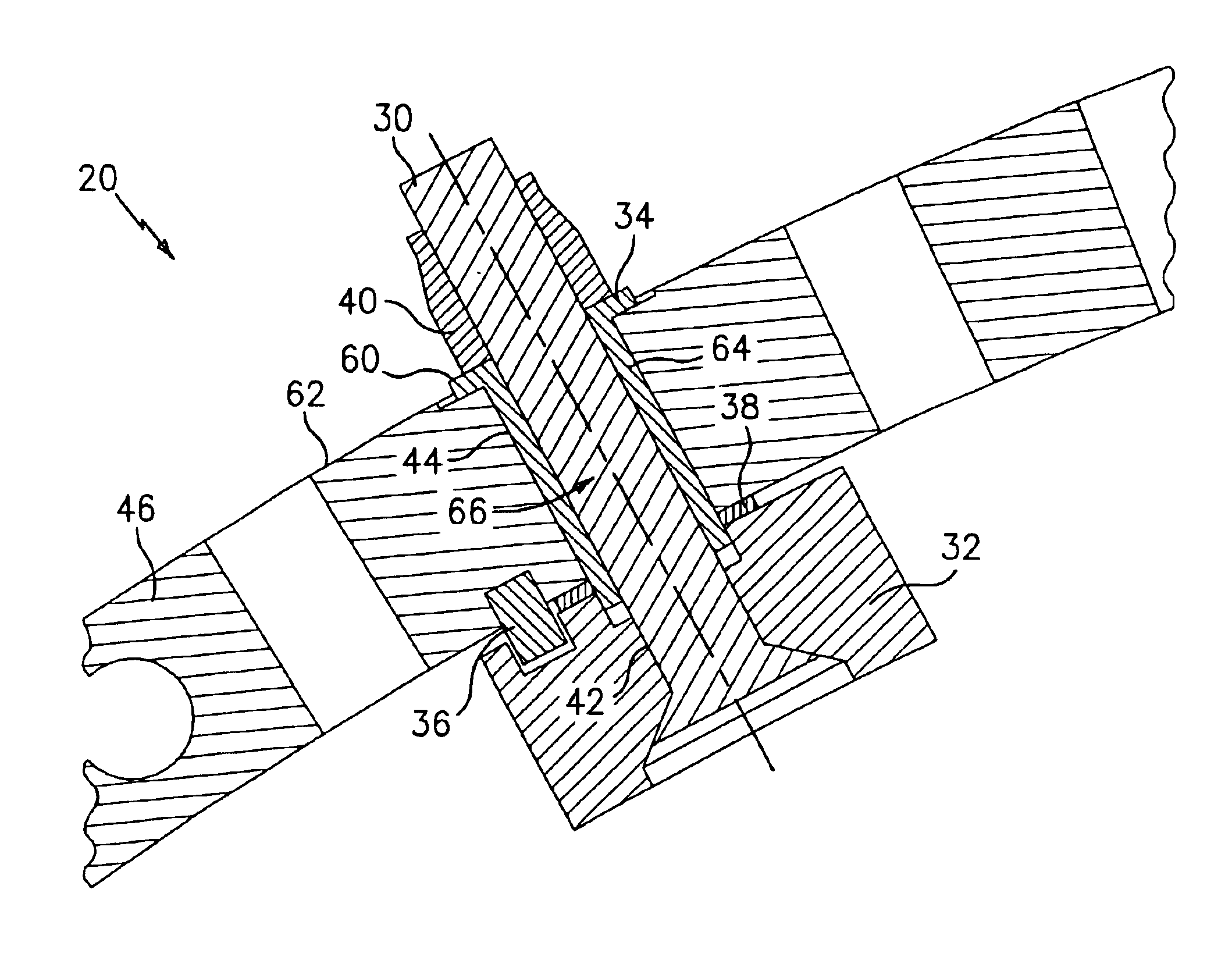
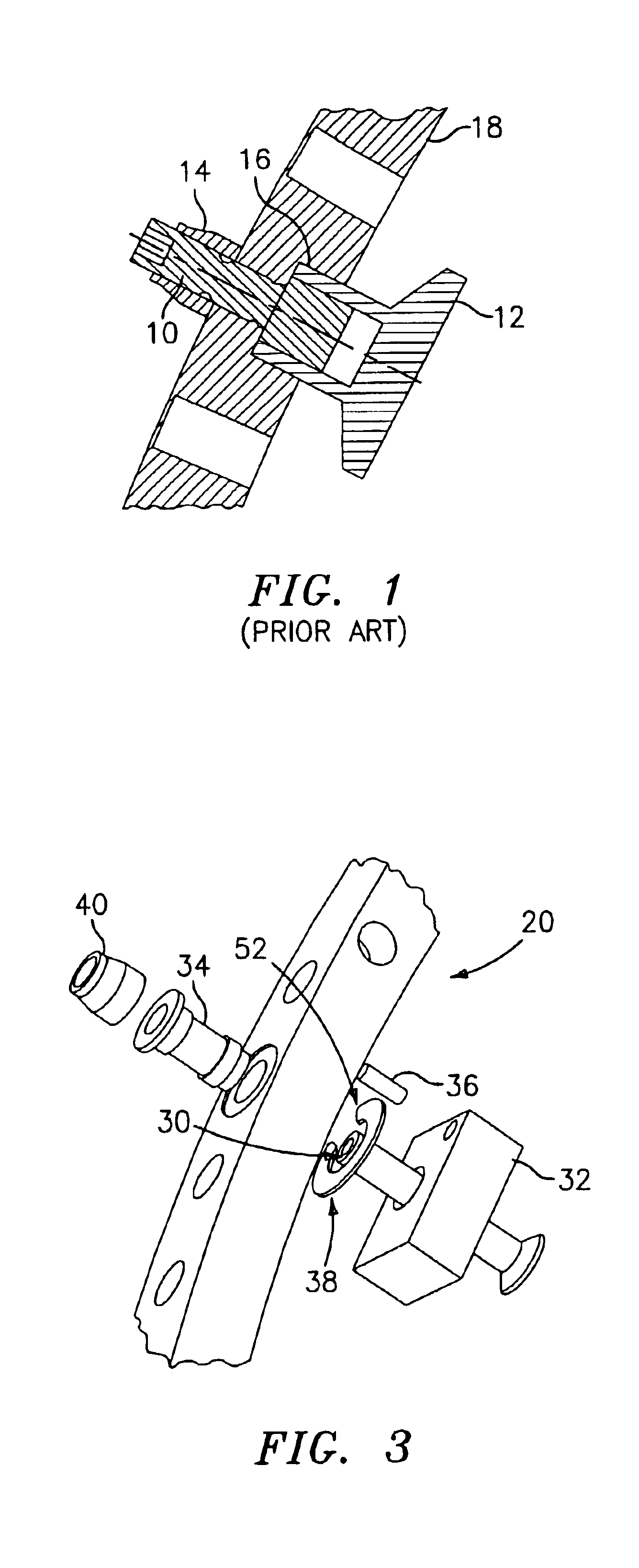
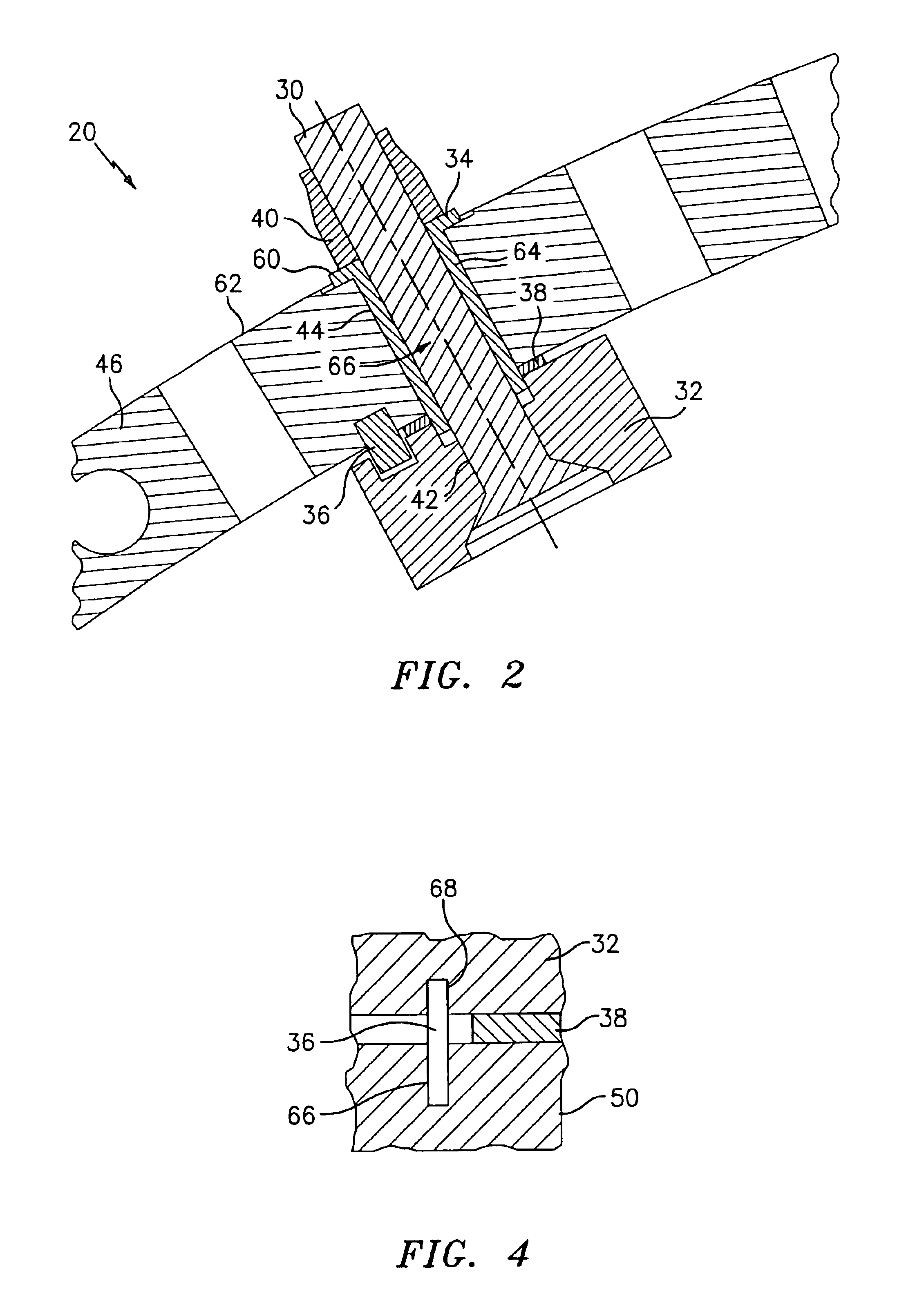
[0019]Referring now to the drawings, FIGS. 2 through 4 illustrate a bumper system for use on a gas turbine engine in accordance with the present invention. The bumper system uses shims to set the bumper gaps. As shown in FIGS. 2 through 4, the bumper system 20 includes a fastener 30, such as a screw or a bolt having a thread at one end, a one-piece composite bumper 32, a shim-lock sleeve 34, a dowel pin 36, a shim 38, and a threaded shear lock collar 40 for engaging the threaded end of the fastener 30. The fastener 30 passes through a bore 42 in the bumper 32 and through a hole 44 in the synchronizing ring 46. As can be seen from FIG. 2, the hole 44 has a diameter greater than the diameter of the fastener 30.

[0020]A suitable composite material for the bumper 32 requires low coefficient of friction (lubricity) to minimize the frictional loading in the system. The material also needs to have dimensional stability and wear resistance to maintain running gaps to minimize the vane angle...


PUM


Abstract

The present invention relates to a bumper system for use with a compressor variable vane system. The bumper system broadly comprises a synchronizing ring, a bumper, a shim for defining a gap between a bumper pad and the bumper, a pin for preventing rotation of the bumper relative to the synchronizing ring, and a device for fully trapping the shim. In a first embodiment, the device for fully trapping the shim comprises a sleeve passing through the synchronizing ring. In a second embodiment, the device for fully trapping the shim comprises a pin which passes through the synchronizing body. In a third embodiment, the device for fully trapping the shim comprises a fastener with a shoulder.

Description

STATEMENT OF GOVERNMENT INTEREST[0001]The present invention was made under Contract No. F33657-91-C-007 with the United States Department of Air Force. The Government of the United States of America may have rights under this contract.BACKGROUND OF THE INVENTION[0002]The present invention relates to an improved shimable bumper system for use in a compressor variable vane system that fully traps the shim in case of lost screw preload and that has an anti-rotation feature.[0003]The main components of a compressor variable vane system are the stator vanes, vane arms, synchronizing rings, bumpers, linkage system, and the actuator. The vane arms are used to control the incidence angle of the vanes in the compressor of gas turbine engines. The vanes are arranged as a stage set around the circumference of the compressor. The arm attaches to each vane spindle which rotates in a bearing mounted in the compressor case. The set of vanes are actuated by a circumferential synchronizing ring that...

Claims


Application Information

Patent Timeline
Patent Type & Authority Patents(United States)
IPC IPC(8): F01D17/16F01D17/00B60R19/24F04D29/56F01B25/02
CPCF01D17/16F05D2300/603F05D2260/30F05B2260/301B60R19/24F01B25/02
Inventor PICKENS, JOHN T.ALEXANDER, PHILLIPBIFULCO, ANTHONY R.CUMMINGS, KEVIN J.
Owner RAYTHEON TECH CORP
Why Eureka
Try Eureka