
Lift and rotate agricultural implement

a technology of agricultural implements and implements, applied in the field of agricultural implements, can solve the problems of large height of implements, limited length of planters, and significant time loss, and achieve the effects of increasing width, lifting and rotating, and providing a lift and rotating planter

Active Publication Date: 2018-08-09
KINZE MFG INC
View PDF6 Cites 1 Cited by
  • Summary
  • Abstract
  • Description
  • Claims
  • Application Information

AI Technical Summary

Benefits of technology

The invention is a lift and rotate planter that aims to improve on existing technologies. It has several advantages, including increased width, decreased stress on the toolbar and rotating actuator, and the use of multiple actuators working in tandem. The planter also includes an anti-rotation link that ensures stability. Additionally, it has a telescoping tongue that allows for longer wings to be rotated while in the transport configuration. Overall, the invention provides a more robust and efficient lift and rotate planter for agricultural purposes.

Problems solved by technology

In addition to the cost of these special-use transport trailers, these planters are limited in length by the practical requirements of having to load the implement on the trailer and to unload it.
This loss of time can be significant in view of the short time typically available when good planting conditions prevail, particularly when numerous fields must be planted using the same implement.
When folded, the implement is much greater in height, frequently causing problems when attempting to pass under bridges, through gates and into storage buildings.
In addition, even with the two outer wing sections folded, because of the increasing size of agricultural implements, the fixed center section may also restrict transport and storage of the implement.
However, lift and rotate planters are not without problems.
Due to the increased sizes of the wings, during lifting, they may tend to want to rotate or walk, with can increase the strain on the toolbar and components thereof.

Method used


Image

  • Lift and rotate agricultural implement
  • Lift and rotate agricultural implement
  • Lift and rotate agricultural implement

Examples


Embodiment Construction

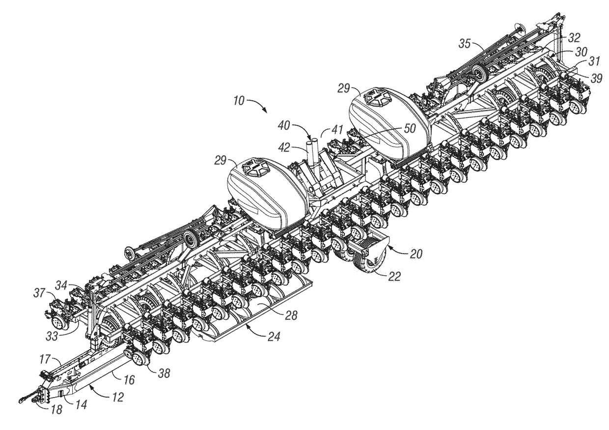
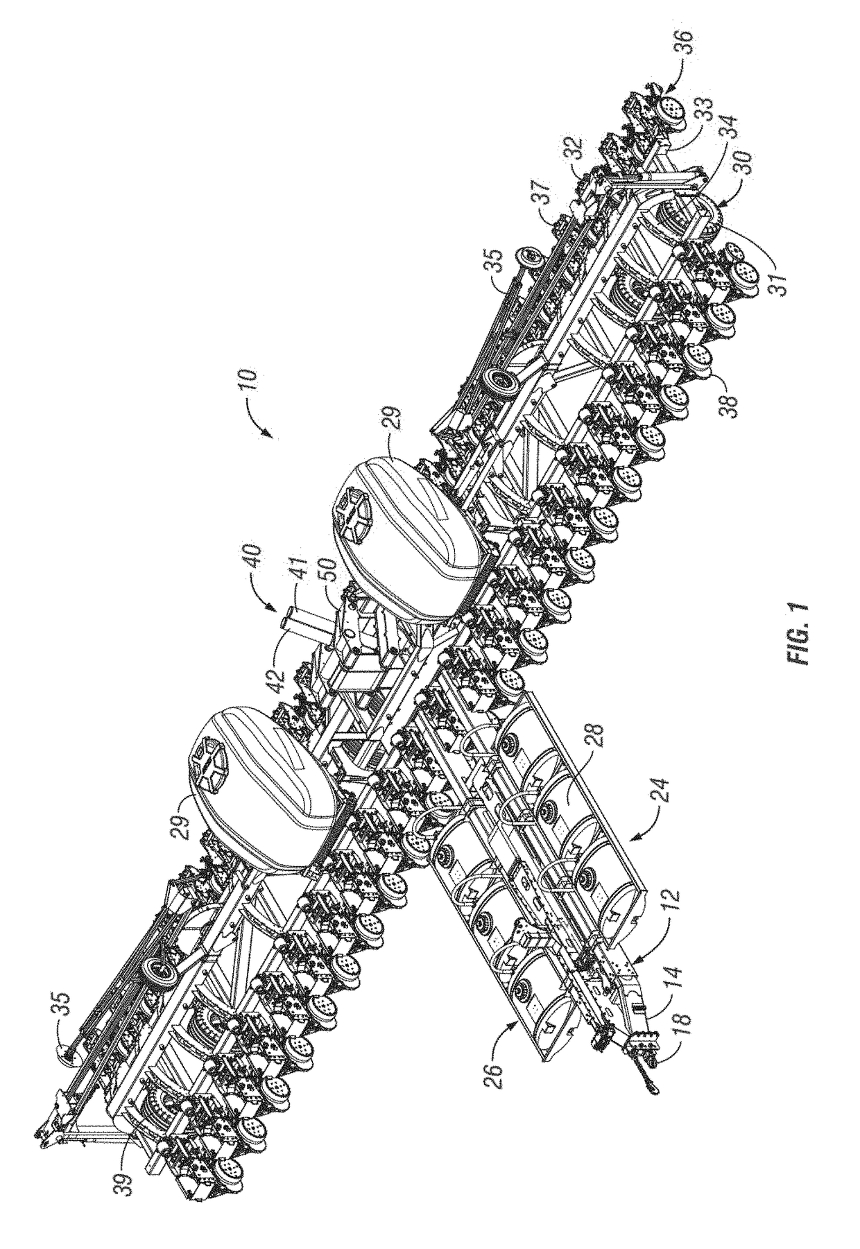
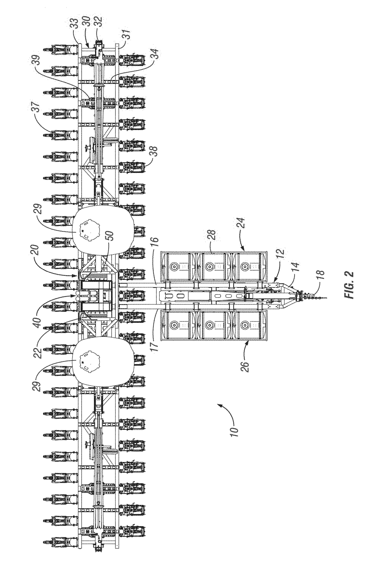
[0074]The invention is directed towards an agricultural planting implement, which may also be known as a planter. The planter is of the type which includes a field use configuration, a turning configuration, and a transport configuration. For example, when in the field use and turning configurations, the planter 10 will include a tongue member extending from a tow vehicle, such as a tractor, with a toolbar with row units that is generally transverse to the tongue. The same general configuration will appear when the planter is in a turning configuration, with the exception that the row units will be at least partially lifted off the ground to allow for the planter 10 to be turned within a field with reduced resistance. However, to transition the planter 10 to a transport configuration, the toolbar and row units attached thereto will be lifted above the ground and to a height where the components of the toolbar are at least partially above the tongue. Next, a rotating mechanism will r...


PUM


Abstract

An agricultural implement includes a toolbar that extends transverse to a tongue when in a field use configuration. The toolbar can be lifted and / or rotated relative to the tongue to transition between a field use and a transport use. A lifting assembly includes one or more actuators and linkage systems to lift the toolbar attached thereto in an arced manner in moving from a field use configuration to a transport configuration. A rotating mechanism can also include one or more actuators to rotate the toolbar about a pivot member. An anti-rotation link includes a member is connected to the toolbar and can be positioned at least partially within a groove to mitigate rotation of the toolbar, such as during the lifting of the toolbar.

Description

CROSS-REFERENCE TO RELATED APPLICATIONS[0001]This application is a Continuation application of U.S. Ser. No. 15 / 133,812, filed Apr. 20, 2016, which claims priority under 35 U.S.C. § 119 to provisional application Ser. No. 62 / 149,777, filed Apr. 20, 2015. The contents of both applications are herein incorporated by reference in their entirety.FIELD OF THE INVENTION[0002]The invention relates generally to agricultural implements. More specifically, but not exclusively, the invention relates to improvements of an agricultural implement that lifts and rotates to transition from a field use to a transport use.BACKGROUND OF THE INVENTIONS[0003]Increased tractor horsepower has resulted in larger implements capable of planting or working a much wider swath in a single pass. Transport of these wide implements from a storage area to a field or from one field to another over roads has become an important design consideration. Some early planters required separate trailers for transport. In add...

Claims


Application Information

Patent Timeline
Patent Type & Authority Applications(United States)
IPC IPC(8): A01B73/00A01C7/20A01B73/06
CPCA01B73/005A01C7/208A01B73/06
Inventor KINZENBAW, JONBLACKWELL, ROBERTLIND, RILEY
Owner KINZE MFG INC
Learn More