Lubrication systems for transmissions

Active Publication Date: 2018-08-09
SIKORSKY AIRCRAFT CORP
View PDF20 Cites 8 Cited by
  • Summary
  • Abstract
  • Description
  • Claims
  • Application Information

AI Technical Summary

Benefits of technology

[0005]A transmission lubrication system includes a controller connected to one or more sensors and one or more flow-metering devices. A feedback loop connects the one or more sensors to the controller to provide the controller with information relating to one or more transmission operating parameters. The controller is operatively connected to the one or more flow-metering devices to intermittently issue lubricant to the transmission element for husbanding lubricant available for issue to the transmission element.

Problems solved by technology

Because transmission operation under reduced lubricant flow conditions can accelerate wear of certain transmission elements, regulatory agencies like the Federal Aviation Administration (FAA) in the United States require that, unless the probability of reduced lubricant flow can be demonstrated to be extremely remote, that it be shown by test that any failure which results in loss of lubricant in any normal use lubrication system will not prevent continued safe operation, although not necessarily without damage, at a torque and rotational speed prescribed by the applicant for continued flight, for at least thirty (30) minutes after perception by the flight crew of the lubrication system failure or loss of lubricant.

Method used


Image

  • Lubrication systems for transmissions
  • Lubrication systems for transmissions
  • Lubrication systems for transmissions

Examples


Embodiment Construction

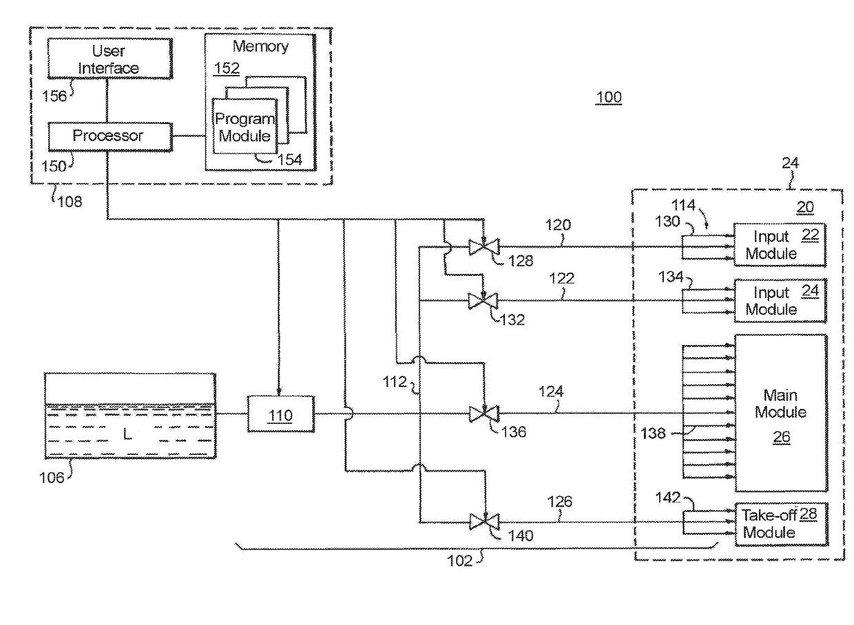
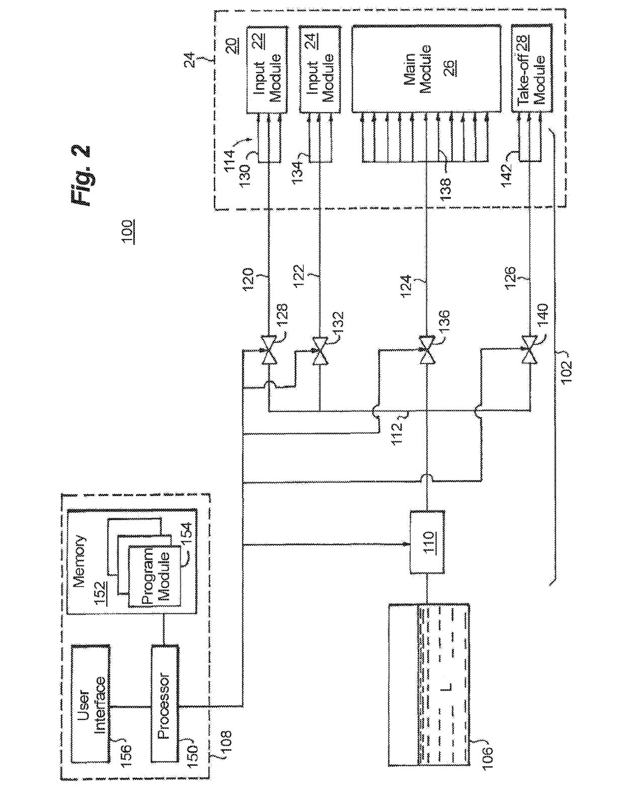
[0016]Reference will now be made to the drawings wherein like reference numerals identify similar structural features or aspects of the subject disclosure. For purposes of explanation and illustration, and not limitation, a partial view of an exemplary embodiment of a lubrication system in accordance with the disclosure is shown in FIG. 1 and is designated generally by reference character 100. Other embodiments of lubrications systems and methods of lubricating transmission elements in accordance with the disclosure, or aspects thereof, are provided in FIGS. 2-4, as will be described. The systems and methods described herein can be used for aircraft transmissions, such as gearboxes for rotary wing aircraft like helicopters, however the invention is not limited to a particular type of aircraft or to aircraft in general.

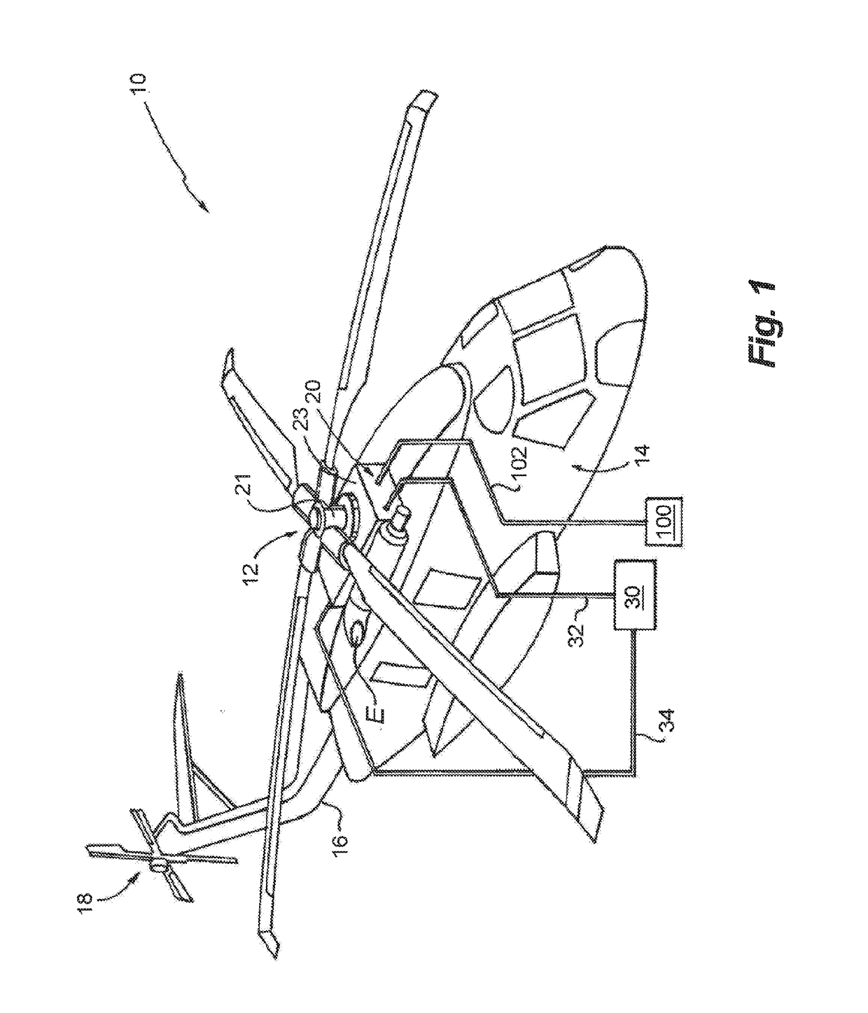
[0017]Referring now to FIG. 1, a rotary wing aircraft 10 is shown. Rotary wing aircraft 10 includes a main rotor system 12, an airframe 14 with a longitudinally extend...


PUM


Abstract

A lubrication system for a transmission includes a flow-metering device and a controller. The controller is operatively associated with the flow-metering device to cause the flow-metering device to intermittently issue lubricant from the flow-metering device into a transmission based on an operating parameter of the transmission.

Description

CROSS-REFERENCE TO RELATED APPLICATIONS[0001]The subject application claims the benefit of priority from U.S. Provisional Application No. 62 / 202,541, filed Aug. 7, 2015, the entire disclosure of which is incorporated herein by reference in its entirety.BACKGROUND OF THE INVENTION1. Field of the Invention[0002]The present disclosure relates to transmissions, and more particularly to lubrication systems such as in transmissions for rotary wing aircraft.2. Description of Related Art[0003]Rotary wing aircraft typically utilize rotor drive transmissions to transfer mechanical rotation from one or more engines to the aircraft rotor system. Rotor drive transmissions typically employ transmission elements like gears and bearings that generate heat due to friction, generally from sliding contact between surfaces of various transmission elements. The heat is removed by the transmission lubrication system, which generally provides lubricant to transmission elements to reduce friction and limit...

Claims


Application Information

Patent Timeline
Patent Type & Authority Applications(United States)
IPC IPC(8): F16H57/04F16N7/38F16N13/22F16N29/02
CPCF16H57/0442F16H57/0456F16N7/38F16N13/22F16N29/02F16H57/0438F16N2210/08F16N2250/40F16N2250/08F16H57/0479B64C27/12F01M1/16F01M1/20F16N2250/00F16N2260/00
Inventor DZIUBA, DYLAN I.BALDYGA, JOHN J.MONTORO, GUY JUANRAMONAS, DAVID
Owner SIKORSKY AIRCRAFT CORP
Why Eureka
Try Eureka