Non-expandable multiple-segment lockable cage

a lockable cage, multiple-segment technology, applied in the field of multiple-segment lockable cage, can solve the problems of lack of manipulation control, and achieve the effect of enhancing attachment with bone and easy steering

Inactive Publication Date: 2018-08-23
EXPANDING ORTHOPEDICS
View PDF2 Cites 9 Cited by
  • Summary
  • Abstract
  • Description
  • Claims
  • Application Information

AI Technical Summary

Benefits of technology

[0004]The present invention seeks to provide a novel, simple articulated device, which includes two or more segments, which can be easily steered and locked in a desired orientation, such as or use in spinal fusion cases or other spinal or bone applications, where a controllable spacer is needed. The device can be made of any medical material compatible for bone utilization, such as but not limited to, titanium or titanium alloy, PEEK (polyether ether ketone), polymers, resorbable materials or any other metal, natural or synthetic material or combinations of them. The surfaces of the device may be regular or irregular, including surfaces that may enhance attachment with bone. The device may have superior and inferior surfaces parallel or tilted to suit any intervertebral space shape.

Problems solved by technology

However, such devices suffer from a lack of manipulation control during the insertion process and while in the intervertebral space, including difficulty in locking the device in the final desired position.

Method used


Image

  • Non-expandable multiple-segment lockable cage
  • Non-expandable multiple-segment lockable cage
  • Non-expandable multiple-segment lockable cage

Examples


Embodiment Construction

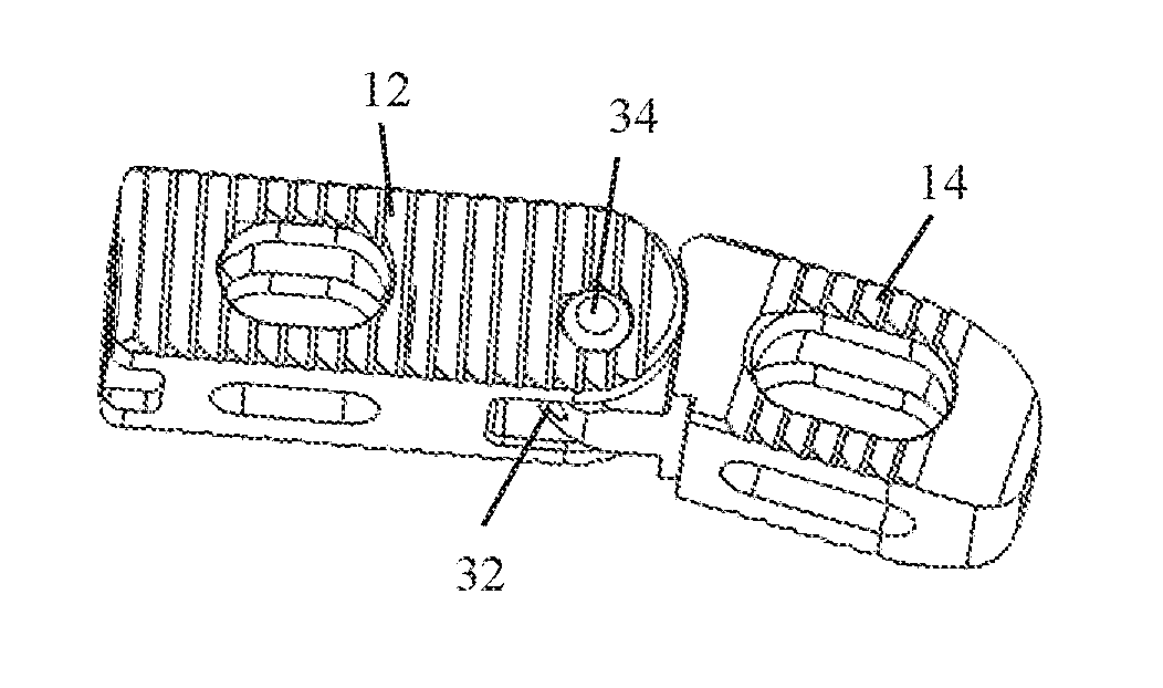
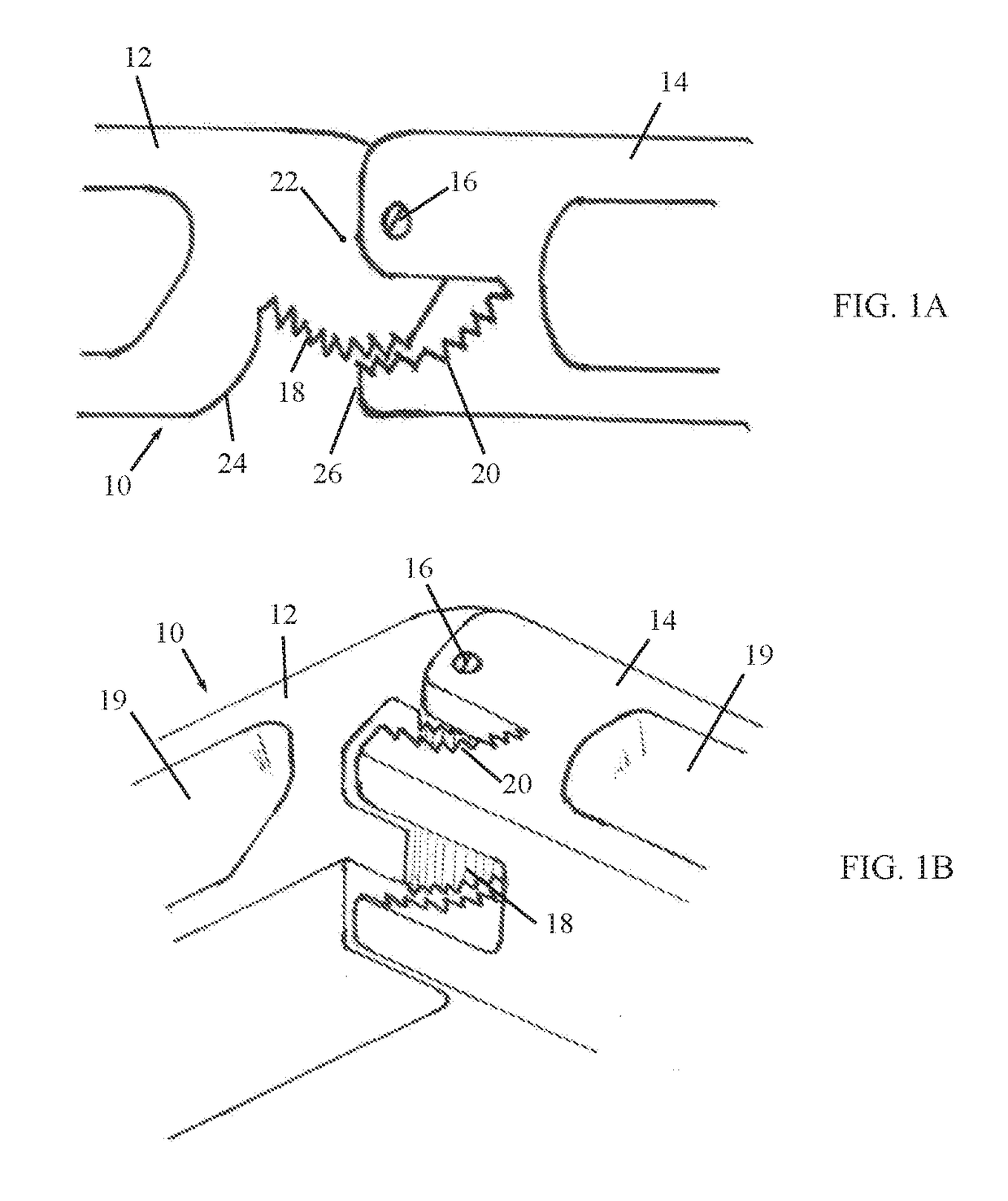
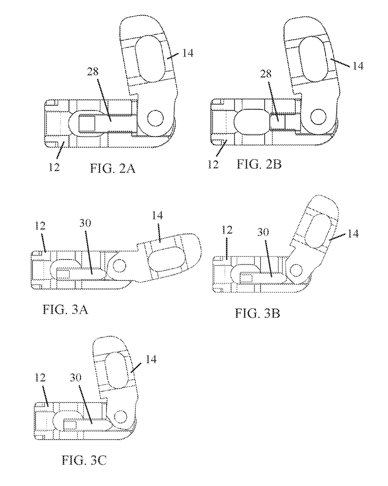
[0023]Reference is now made to FIGS. 1A-1B, which illustrate a cage device 10, in accordance with a non-limiting embodiment of the present invention.

[0024]Cage device 10 includes first and second segments 12 and 14 connected by an eccentric hinge 16. The first and second segments 12 and 14 are formed with cooperating first and second ratchets 18 and 20, respectively, which ratchet together as first segment 12 pivots about hinge 16 relative to second segment 14. The hinge 16 is eccentric, which means the pivot point of the hinge is off-center from the center point 22 of the first ratchet 18, that is, the origin of the radius of curvature of the curved contour on which the ratchet teeth are formed. The segments can be steered in one direction in controlled steps per the teeth spacing of the ratchet system, until reaching a final limit when a first stopper portion 24 of first segment 12 abuts against a second stopper portion 26 of second segment 14. The segments may include bone graft ...


PUM


Abstract

A cage device includes first and second segments pivotally connected by a hinge. Pivoted movement of the segments with respect to each other is limited by a first stopper portion of the first segment abutting against a second stopper portion of the second segment.

Description

FIELD OF THE INVENTION[0001]The present invention generally relates to devices and methods for spinal fusion or other spinal techniques and particularly to a multiple-segment lockable cage for such spinal techniques.BACKGROUND OF THE INVENTION[0002]Cages for spine fusion are used to fuse two or more vertebrae for treatment of different pathologies. The cages improve the anterior column stability, preserve the disc space height, include chambers for bone graft that enhance the fusion process and are used in some cases with the addition of supplementary screws. The most efficient cages have a large contact surface for contacting both vertebrae endplates, superior and inferior, and are able to be located preferably in the periphery of the disc space.[0003]Simple cages include a spacer of rectangular, circular or trapezoidal shape made of a single segment device. If one cage is insufficient to cover the space to be treated, more than one cage can be introduced into the space. Some cages...

Claims


Application Information

Patent Timeline
Patent Type & Authority Applications(United States)
IPC IPC(8): A61F2/44A61F2/46
CPCA61F2/4425A61F2/4611A61F2002/448A61F2002/4475A61F2002/443A61F2/4455A61F2002/30471A61F2002/30507A61F2002/30522A61F2002/30523A61F2002/30528A61F2002/30538A61F2002/30593
Inventor LEVY, MARK M.ISHAY, ERANHLEIHIL, JAFFARGUY, ASSAF
Owner EXPANDING ORTHOPEDICS
Why Eureka
Try Eureka