Removable container shipping frame for vehicle

a frame and container technology, applied in the field of transportation systems, can solve the problems of difficult to pull the frame from the container, heavy weight of the removable system, and serious limitations of the known frame system

Active Publication Date: 2018-08-23
SAER MATT
View PDF2 Cites 9 Cited by
  • Summary
  • Abstract
  • Description
  • Claims
  • Application Information

AI Technical Summary

Benefits of technology

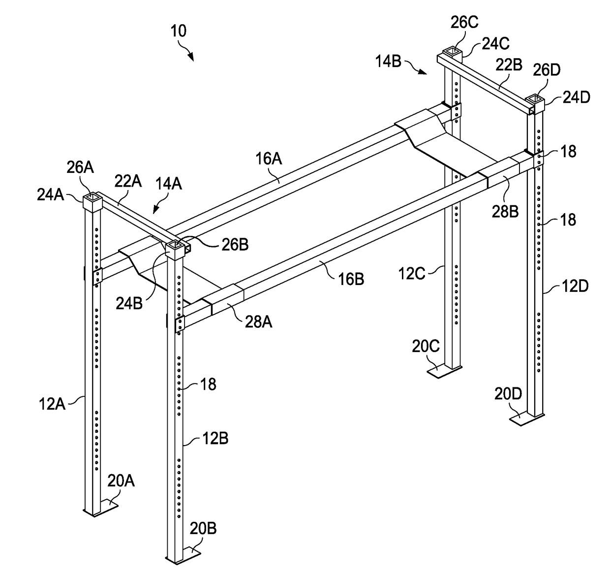
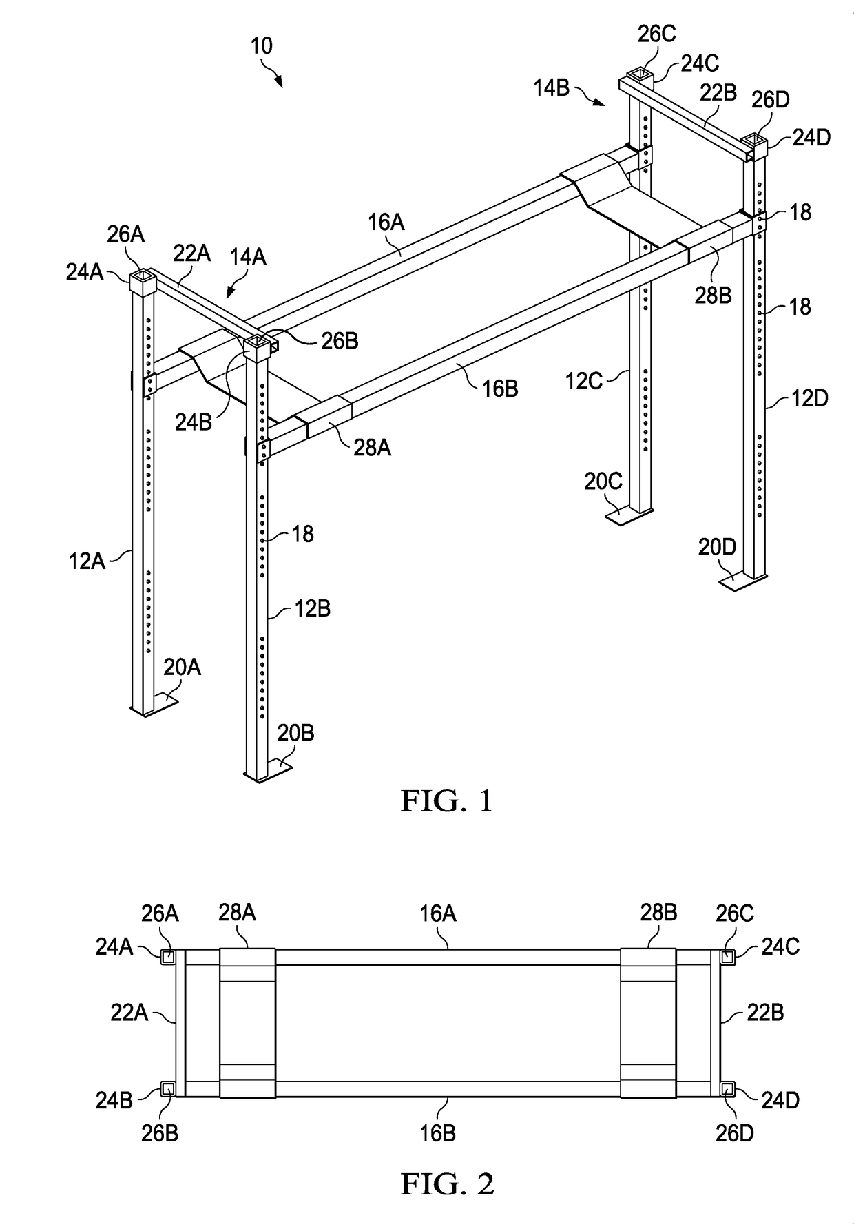
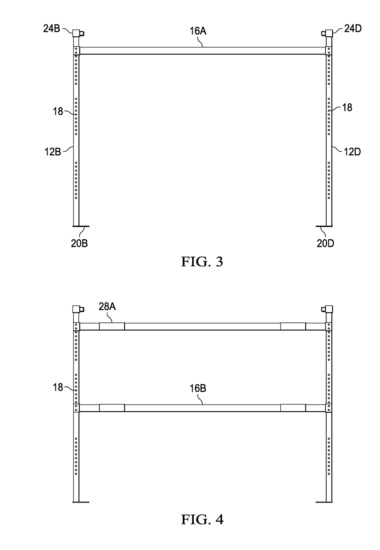
[0010]The frame system is modular and can be assembled and disassembled within or out of the container. The frame system includes 4 posts that extend vertically upward from the floor of the container. The posts may be attached to the floor of the container and / or attached to the walls of the container. The posts are connected to crossbars to set the width of the frame. Rails are secured to each pair of posts to set the length of the frame system. At this time the rails may be placed perpendicular to the posts or at an angle relative to the posts depending on the desired configuration and vehicle being transported. Once the frame is assembled the vehicle adaptor is positioned on the rails to secure the vehicle to the frame system. The vehicle is then positioned on the vehicle adaptors and then secured into position. The vehicle may also be secured by additional securing devices, e.g., straps, chains, cables, etc. The container can then be transported to the disembarking location so that the vehicle can be removed from the frame system. The frame system is then disassembled and stored or transported back to the originator. Although, the frame system is designed to be disassembled and removable it may be advantageous in some embodiments to permanently (or semi-permanently) fix the frame system in the container. The frame system can transport cars, trucks, ATVs, water crafts, boats, carts, trailers, conduits, building materials, culvers, and any other object that can be positioned within the frame system.
[0011]The present invention provides a removable frame system for supporting a vehicle for transport within a container comprising: a first pair of frame supports connected and stabilized by a first cross member; a second pair of frame supports opposite the first pair of frame supports and connected and stabilized by a first cross member; a first rail secured at a first end to one of the first pair of frame supports and secured at a second end to one of the second pair of frame supports; a second rail secured at a first end to one of the first pair of frame supports and secured at a second end to one of the second pair of frame supports; a first vehicle adaptor positioned from the first rail to the second rail; and a second vehicle adaptor positioned from the first rail to the second rail.
[0012]The present invention provides a method of removable installing a frame system in a container for supporting a vehicle for transport comprising the steps of: positioning a first pair of frame supports in a container, wherein each of the first pair of frame supports comprise a plurality of first apertures along the length of each of the first pair of frame supports; connecting a first crossbar to each of the first pair of frame supports to stabilize the first pair of frame supports; positioning a second pair of frame supports in the container opposite the first pair of frame supports, wherein each of the second pair of frame supports comprise a plurality of second apertures along the length of each of the second pair of frame supports; connecting a second crossbar to each of the second pair of frame supports to stabilize the second pair of frame supports; positioning at a first end of a first rail on the first member of the first pair of frame supports; inserting a first fastener through the first end and into one or more of the plurality of first apertures to secure the first rail to the first member of the first pair of frame supports; positioning at a second end of a first rail on the first member of the second pair of frame supports; inserting a second fastener through the second end and into one or more of the plurality of second apertures to secure the first rail to the first member of the second pair of frame supports; positioning at a first end of a second rail on the second member of the first pair of frame supports; inserting a first fastener through the first end of a second rail and into one or more of the plurality of first apertures to secure the second rail to the second member of the first pair of frame supports; positioning at a second end of the second rail on the second member of the second pair of frame supports; inserting a second fastener through the second end of the second rail and into one or more of the plurality of second apertures to secure the second rail to the second member of the second pair of frame supports; positioning a first vehicle adaptor over the first end of a first rail and extending to the first end of a second rail; and positioning a second vehicle adaptor over the second end of a first rail and extending to the second end of a second rail.
[0013]The present invention provides a method of transporting one or more vehicles using a removable frame system assembled in an existing transport container comprising the steps of: providing an existing container; installing a removable frame system in the existing container by positioning a first pair of frame supports in a container, wherein each of the first pair of frame supports comprise a plurality of first apertures along the length of each of the first pair of frame supports; connecting a first crossbar to each of the first pair of frame supports to stabilize the first pair of frame supports; positioning a second pair of frame supports in the container opposite the first pair of frame supports, wherein each of the second pair of frame supports comprise a plurality of second apertures along the length of each of the second pair of frame supports; connecting a second crossbar to each of the second pair of frame supports to stabilize the second pair of frame supports; positioning at a first end of a first rail on the first member of the first pair of frame supports; inserting a first fastener through the first end and into one or more of the plurality of first apertures to secure the first rail to the first member of the first pair of frame supports; positioning at a second end of a first rail on the first member of the second pair of frame supports; inserting a second fastener through the second end and into one or more of the plurality of second apertures to secure the first rail to the first member of the second pair of frame supports; positioning at a first end of a second rail on the second member of the first pair of frame supports; inserting a first fastener through the first end of a second rail and into one or more of the plurality of first apertures to secure the second rail to the second member of the first pair of frame supports; positioning at a second end of the second rail on the second member of the second pair of frame supports; inserting a second fastener through the second end of the second rail and into one or more of the plurality of second apertures to secure the second rail to the second member of the second pair of frame supports; positioning a first vehicle adaptor over the first end of a first rail and extending to the first end of a second rail; and positioning a second vehicle adaptor over the second end of a first rail and extending to the second end of a second rail; securing the removable frame system to the existing container by attaching the at least one of the first pair of frame supports, at least one of the second pair of frame supports or a combination thereof are attached to a wall of the container; attaching the at least one of the first pair of frame supports, at least one of the second pair of frame supports or a combination thereof are attached to a floor of the container or both; loading a first vehicle under the first vehicle adaptor and the second vehicle adaptor and positioning a second vehicle on the first vehicle adaptor and the second vehicle adaptor; transporting the existing container to a destination; unloading the first vehicle and the second vehicle; disassembling the removable frame system to form a disassembled removable frame system; and storing the disassembled removable frame system, shipping the disassembled removable frame system or storing the disassembled removable frame system and shipping the disassembled removable frame system.
[0014]For any of the embodiments listed herein the methods can further include the step of positioning a vehicle on the first vehicle adaptor and the second vehicle adaptor. The step of positioning a first vehicle under the first vehicle adaptor and the second vehicle adaptor and positioning a second vehicle on the first vehicle adaptor and the second vehicle adaptor. The first rail may be parallel to the second rail. The first rail may be parallel to the second rail and perpendicular to the first pair of frame supports and the second pair of frame supports. The e first rail may be parallel to the second rail and at an angle relative to the first pair of frame supports. The first rail may be parallel to the second rail and at an angle of between 25 and 90 degrees relative to the first pair of frame supports. The first rail may be parallel to the second rail and at an angle of between 35 and 50 degrees relative to the first pair of frame supports. The at least one of the first pair of frame supports, at least one of the second pair of frame supports or a combination thereof may be attached to a wall of the container. The at least one of the first pair of frame supports, at least one of the second pair of frame supports or a combination thereof may be attached to a floor of the container. The additional step may include one or more hook pins comprising a hooked end, the one or more hook pins being insertable through a selected one of the plurality of first apertures, the plurality of second apertures or both and the hooked end of the one or more hook pins being engageable with standard fastening hoops attached to top and / or bottom side rails of the container. The container may be a simple container, cargo container, freight container, ISO container, shipping container, sea container, ocean container, container van, CONEX® box, sea box, c can, a 53-foot container, intermodal container, or similar container.

Problems solved by technology

Transport frame systems have been known in the art; however, given the unique requirements of securing a vehicle for transport, the known frame systems have serious limitations.
The removable systems are often heavy and difficult to pull the frames from the container.

Method used


Image

  • Removable container shipping frame for vehicle
  • Removable container shipping frame for vehicle
  • Removable container shipping frame for vehicle

Examples


Embodiment Construction

[0022]While the making and using of various embodiments of the present invention are discussed in detail below, it should be appreciated that the present invention provides many applicable inventive concepts that can be embodied in a wide variety of specific contexts. The specific embodiments discussed herein are merely illustrative of specific ways to make and use the invention and do not delimit the scope of the invention.

[0023]To facilitate the understanding of this invention, a number of terms are defined below. Terms defined herein have meanings as commonly understood by a person of ordinary skill in the areas relevant to the present invention. Terms such as “a”, “an” and “the” are not intended to refer to only a singular entity, but include the general class of which a specific example may be used for illustration. The terminology herein is used to describe specific embodiments of the invention, but their usage does not delimit the invention, except as outlined in the claims.

[...


PUM


Abstract

The present invention provides a removable frame system for transporting vehicles in a container. The frame system is be assembled in the container, the vehicles are loaded on the frame system, the container is shipped to the location, the vehicles are unloaded from the frame system, and the frame system is disassembled and returned to the manufacture or stored for later use.

Description

CROSS-REFERENCE TO RELATED APPLICATIONS[0001]None.TECHNICAL FIELD OF THE INVENTION[0002]The present invention relates in general to the field of transport systems, and more particularly, to collapsible transport systems for transporting vehicles.STATEMENT OF FEDERALLY FUNDED RESEARCH[0003]None.INCORPORATION-BY-REFERENCE OF MATERIALS FILED ON COMPACT DISC[0004]None.BACKGROUND OF THE INVENTION[0005]Without limiting the scope of the invention, its background is described in connection with transport systems. Transport frame systems have been known in the art; however, given the unique requirements of securing a vehicle for transport, the known frame systems have serious limitations. For example, the frame system must be strong enough to support the weight of the vehicle and sturdy enough to maintain stability for the vehicle. In addition, there are different types of frame systems available, some systems are installed permanently in the container, while others are removably installed i...

Claims


Application Information

Patent Timeline
Patent Type & Authority Applications(United States)
IPC IPC(8): B65D85/68B65D90/00
CPCB65D85/68B65D90/006B60P3/07B65D2585/6867B65D90/0053B60P3/08B60P3/06B60P3/077B61D3/166B61D3/18B61D3/188B62D33/02B63B25/00B63B25/004B63B25/008B63B25/20B63B25/24B63B2025/245B63B2025/285B65D85/62B65D88/129B65D90/004B65D90/0073
Inventor SAER, MATT
Owner SAER MATT
Why Eureka
Try Eureka