Anti-glare type vehicle road signboard and road lane identification device

Active Publication Date: 2018-08-30
KIM SUG BAE +4
View PDF3 Cites 0 Cited by
  • Summary
  • Abstract
  • Description
  • Claims
  • Application Information

AI Technical Summary

Benefits of technology

The invention is about a device that prevents glare for drivers by using infrared light to capture images of a road sign and lane, and then projecting them onto the road surface using a figure projection unit. As the vehicle moves, the device synchronizes with the movement of the road signs and lanes, preventing glare and assisting drivers with safe driving by clearly identifying the road signs and lanes.

Problems solved by technology

However, because road signs are poorly visible to the driver unless the high beams of the headlamps are turned on, and because light does not reach the road signboard and the road lane on a cloudy day or a foggy day even when the high beams are turned on, the driver may not recognize guidance text and the road lane.
In other words, conventionally, when driving a vehicle in the city and an irradiation distance of a headlamp is no greater than 30 m, an irradiation angle of the headlamp is out of a range in which the headlamp may illuminate a road signboard, and thus there is a problem in that the driver passes a destination because the driver may not identify the road signboard, or a serious accident is caused due to slowing down in order to identify the road signboard.
On the other hand, conventionally, when the high beams are turned on to identify the road signboard and an oncoming vehicle approaches, the high beams are urgently required to be switched to lower setting, and thus there is a problem in that the vehicle passes the road signboard such that the driver may not identify the road signboard, or when the timing of switching from a higher setting to a lower setting is missed, a driver of the oncoming vehicle receives glare such that a serious accident is caused.
Further, conventionally, when the road signboard is used for a long time in the road lane, the paint of the road signboard is gradually separated and the driver may not identify the road signboard, and thus there is a problem in that the vehicle collides with a vehicle traveling in a neighboring lane.

Method used


Image

  • Anti-glare type vehicle road signboard and road lane identification device
  • Anti-glare type vehicle road signboard and road lane identification device
  • Anti-glare type vehicle road signboard and road lane identification device

Examples


Embodiment Construction

[0028]In this process, thicknesses of lines, sizes of components, or the like shown in the drawings may be exaggerated for clarity and convenience of explanation. Some terms described below are defined by considering functions in embodiments of the invention and meanings may vary depending on, for example, a user or operator's intention or customs. Therefore, the meanings of terms should be interpreted based on the scope throughout this specification.

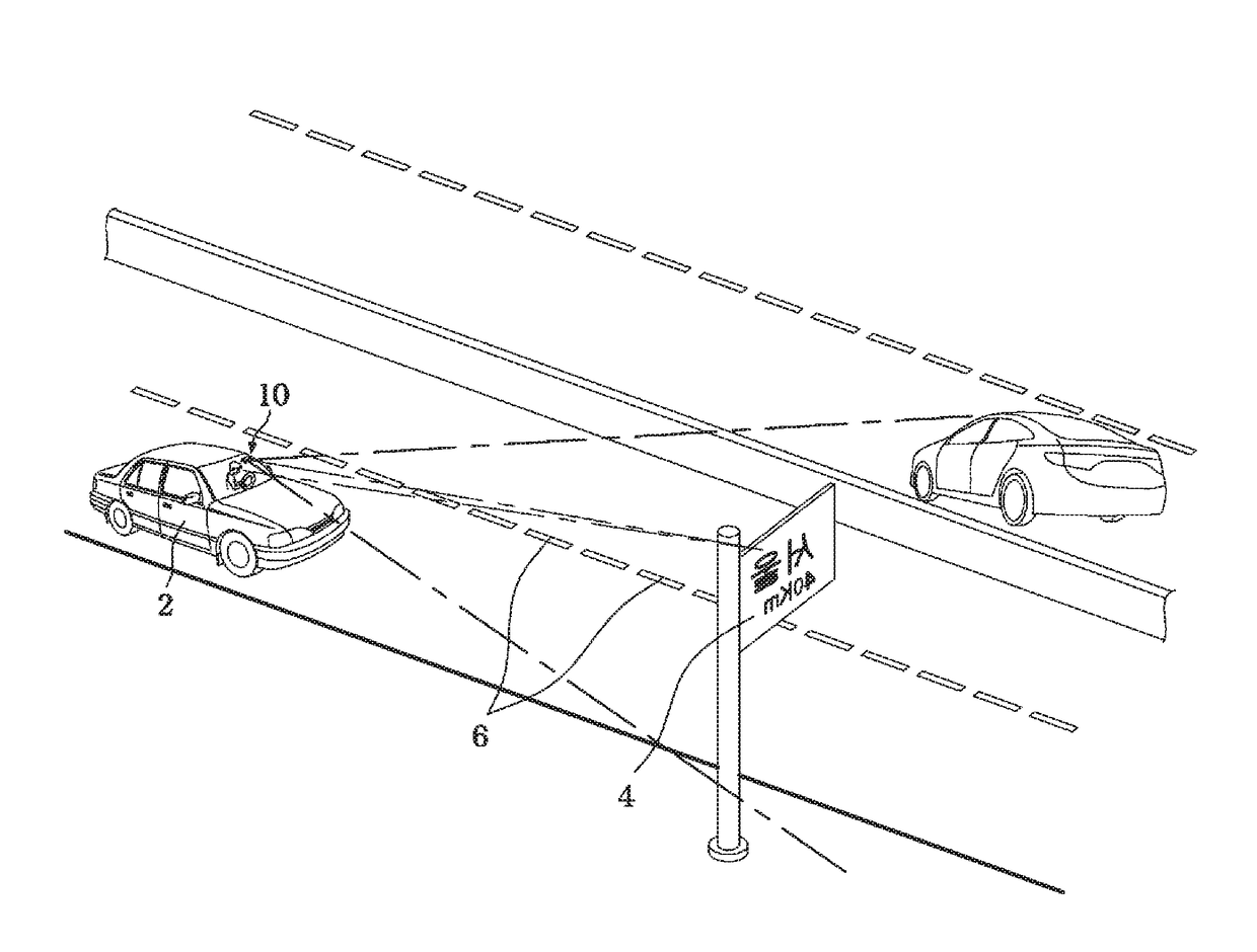
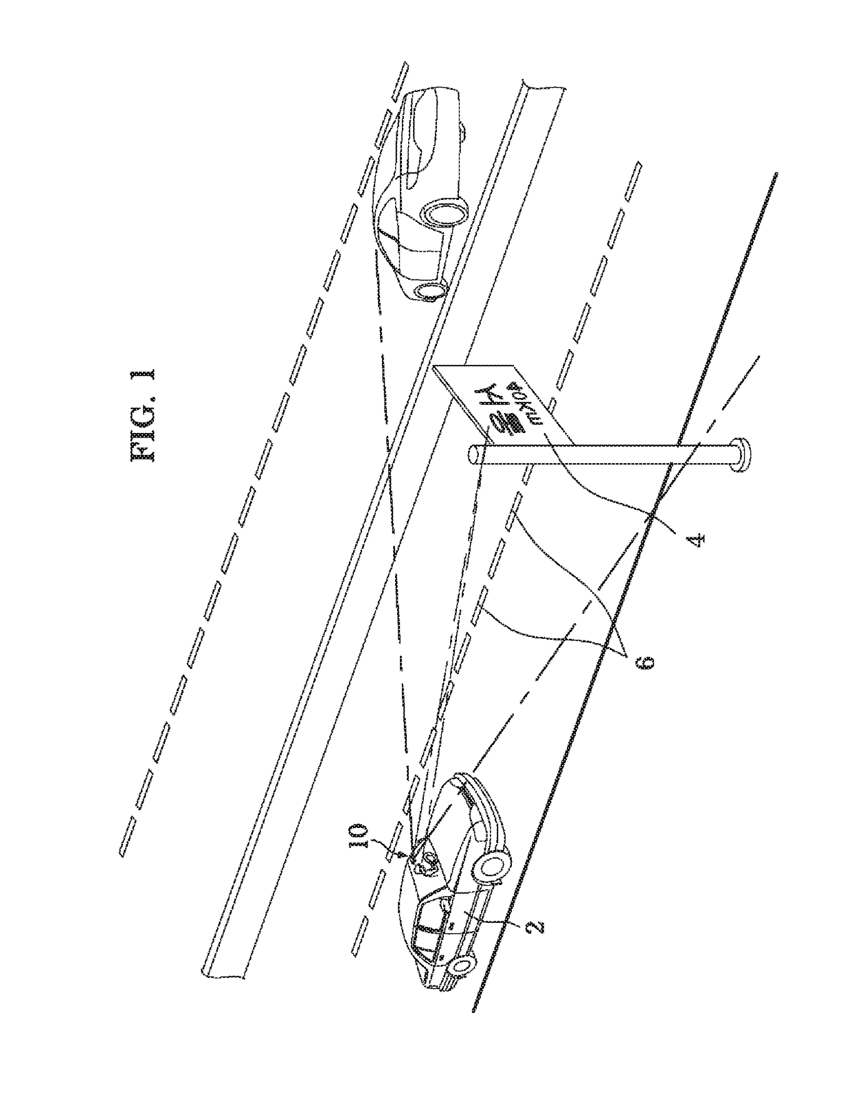
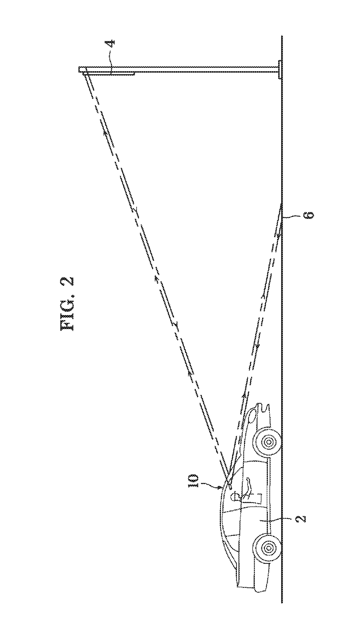
[0029]FIG. 1 is a perspective view showing a state in which an anti-glare type vehicle road signboard and road lane identification device according to an embodiment of the present invention is used on a road, FIG. 2 is a side view showing a state in which the anti-glare type vehicle road signboard and road lane identification device according to the embodiment of the present invention is used on a road, FIG. 3 is a perspective view of the anti-glare type vehicle road signboard and road lane identification device according to the embodim...


PUM


Abstract

An anti-glare type vehicle road signboard and a road lane identification device is provided. The anti-glare type vehicle road signboard and road lane identification device includes: a light-irradiating unit provided in a vehicle for irradiating a non-visible light beam to the front of the vehicle while traveling; an image photographing unit for photographing an image reflected onto the road signboard and the road lane from the light irradiated by the light irradiating unit; and a shape projecting unit for transmitting an image signal photographed by the image photographing unit while traveling and projecting a high luminance light in a state wherein the shapes of the road lane and the road signboard overlap each other to thereby have the road signboard and the road lane clearly seen.

Description

CROSS-REFERENCE TO RELATED APPLICATIONS[0001]This application claims priority to PCT Application No. PCT / KR2016 / 009059, having a filing date of Aug. 18, 2016, based on KR 10-2015-0124388, having a filing date of Sep. 2, 2015, the entire contents both of which are hereby incorporated by reference.FIELD OF TECHNOLOGY[0002]The following relates to an anti-glare type vehicle road signboard and road lane identification device, and more particularly, to an anti-glare type vehicle road signboard and road lane identification device in which, by irradiating a light irradiation unit with a non-visible light beam such as an infrared ray or the like such that an image signal obtained in an image capturing unit by capturing reflected light selectively reflected by retro-reflective materials contained in a road signboard and a road lane is projected by a figure projection unit, when a vehicle moves forward, left, and right and oscillates up and down, the image capturing unit and the figure projec...

Claims


Application Information

Patent Timeline
IPC IPC(8): B60Q1/16B60Q1/24H04N5/33G06K9/00H04N5/217
CPCB60Q1/16B60Q1/24H04N5/33G06K9/00798G06K9/00818H04N5/217B60Q2300/056B60Q2300/42B60Q1/02F21S2/00H04N9/3176B60Q1/249B60Q2400/50B60Q1/268H04N23/56H04N23/20G06V20/582G06V20/588H04N23/81
Inventor KIM, SUG BAENAM, JIN SOOHA, HONG KIKIM, SUN MIKIM, JONG HO
Owner KIM SUG BAE
Why Eureka
Try Eureka