Proximal Femur Hook Plate

a proximal femur and hook plate technology, applied in the field of proximal femur hook plate, can solve the problem of difficult fixing of the bone pla

Active Publication Date: 2018-09-13
DEPUY SYNTHES PROD INC
View PDF0 Cites 5 Cited by
  • Summary
  • Abstract
  • Description
  • Claims
  • Application Information

AI Technical Summary

Problems solved by technology

In some cases, however, particularly for periprosthetic fractures, fixation of the bone plate may be difficult where, for example, an implant such as a THA (Total Hip Arthroplasty) has previously been implanted.

Method used


Image

  • Proximal Femur Hook Plate
  • Proximal Femur Hook Plate
  • Proximal Femur Hook Plate

Examples


Embodiment Construction

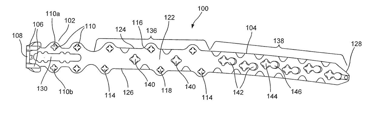
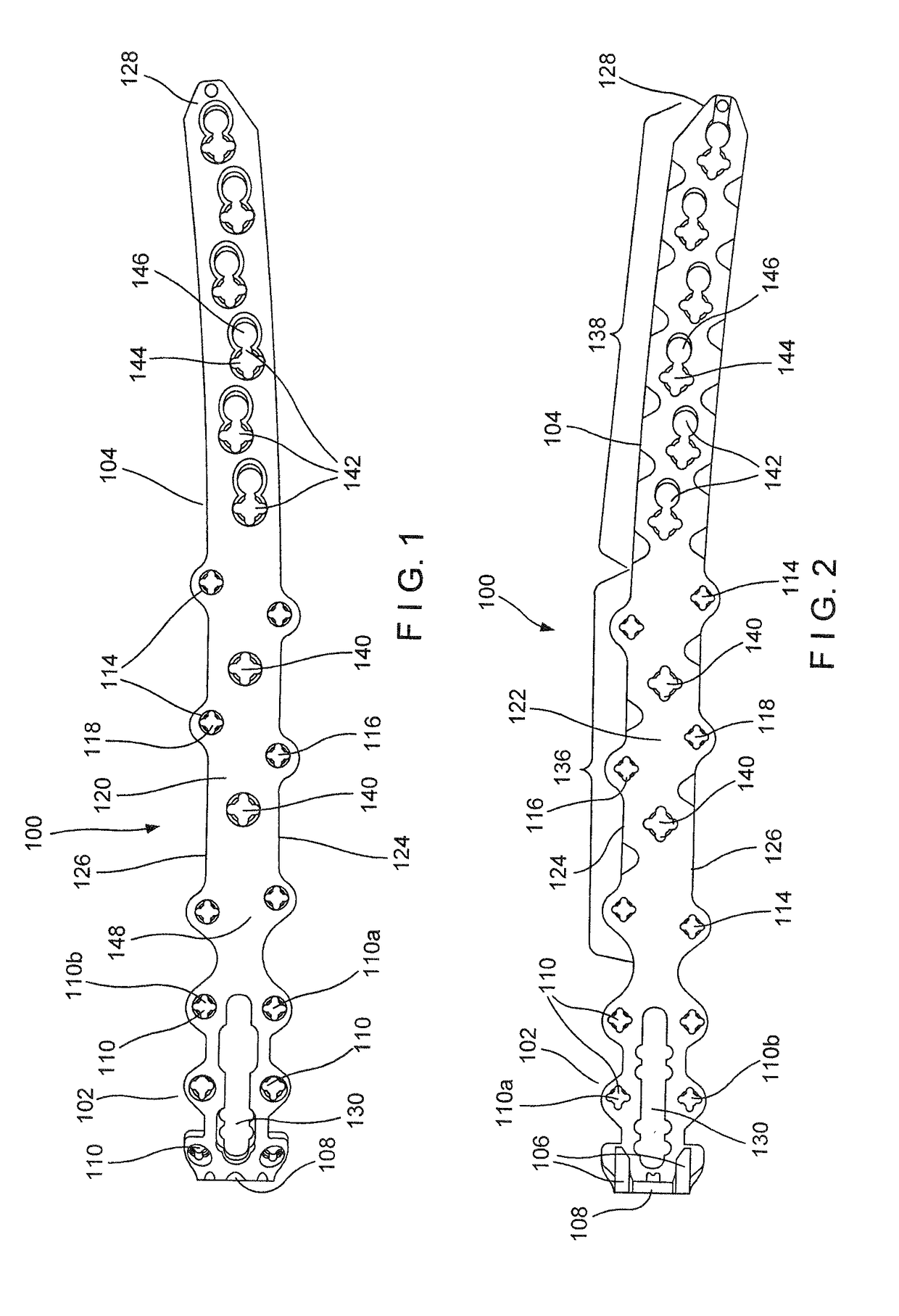
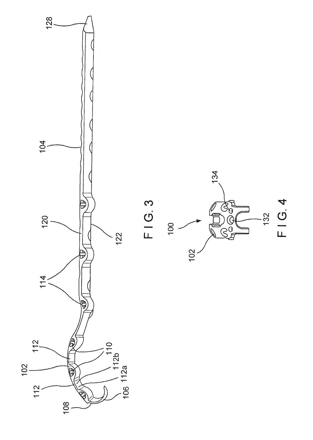
[0011]The present invention may be understood with respect to the following description and the appended drawings, wherein like elements are referred to with the same reference numerals. The present invention relates to the treatment of fractures and, in particular, relates to the treatment of periprosthetic proximal femur fractures. Exemplary embodiments describe a bone plate comprising a head portion configured to be positioned over a portion of a greater trochanter of a femur and a shaft portion extending distally therefrom to be positioned over a portion of a shaft of the femur. The head portion may include a pair of hooks extending from a proximal end thereof to engage a superior ridge of the greater trochanter. The head portion may also include both cable holes for providing cable compression of the greater trochanter and bone fixation element holes for preventing greater trochanteric escape. The shaft portion includes a plurality of pairs of holes on opposite sides of the sha...


PUM


Abstract

A bone plate for treating periprosthetic fractures includes a head portion to be positioned along a greater trochanter of a bone. The head portion includes pairs of bone fixation element receiving openings extending therethrough from a first surface of the plate which, when the plate is in an operative position, faces away from the bone, and a second surface which, when the plate is in the operative position, faces toward the bone. A pair of cable holes extend through the head portion from a first longitudinal side connecting the first and second surfaces to a second longitudinal side connecting the first and second surfaces. The head portion includes a pair of hooks for engaging a superior ridge of the greater trochanter. The plate also includes a shaft portion extending distally from the head portion to extend along a portion of the bone distal of the greater trochanter.

Description

PRIORITY CLAIM[0001]This present application claims priority to U.S. Provisional Patent Application Ser. Nos. 62 / 470,766 and 62 / 470,753 both filed on Mar. 13, 2017 the entire disclosure of both is expressly incorporated herein by reference.BACKGROUND[0002]Proximal femur fractures are often treated with a bone plate positioned on an outer surface of the femur extending across a fracture site. In some cases, however, particularly for periprosthetic fractures, fixation of the bone plate may be difficult where, for example, an implant such as a THA (Total Hip Arthroplasty) has previously been implanted. In these cases, bone fixation elements to fix the plate to the bone must be inserted through the bone without interfering with a stem of the THA or other intramedullary device.SUMMARY[0003]The present embodiments are directed to a bone plate for treating periprosthetic fractures comprises a head portion sized and shaped to be positioned along a greater trochanter of a bone, the head port...

Claims


Application Information

Patent Timeline
Patent Type & Authority Applications(United States)
IPC IPC(8): A61B17/74A61B17/80
CPCA61B17/742A61B17/8004A61B17/74A61B17/80A61B17/8061A61B17/7035A61B17/7037A61B17/7038A61B17/7041A61B17/7049A61B2017/7073A61B17/8057
Inventor KOAY, KENNYGALIE, JESSICAPROBST, TROYFATONE, PETERFRITZ, BRYANBRACE, MIKECHAMPION, GLENNAHAIDUKEWYCH, GEORGE J.STOFFEL, KARLCOLLINGE, CORY A.LIPORACE, FRANK A.ZIRAN, BRUCE H.
Owner DEPUY SYNTHES PROD INC
Why Eureka
Try Eureka