Highly versatile and easy to assemble high-strength support assembly

Inactive Publication Date: 2018-09-20
SONG PING SHANG
View PDF14 Cites 2 Cited by
  • Summary
  • Abstract
  • Description
  • Claims
  • Application Information

AI Technical Summary

Benefits of technology

This patent describes a support assembly structure that is easy to assemble and strong. It involves a fastening cover that can be slid onto a C-type steel and a flexible internal stand. The internal stand is fastened to the cover from inside the C-type steel, allowing the C-type steel to be utilized on its C side for securing a support. The assembly also includes one or more connecting plates that can be used to join C-type steels and adapt them for a corner, making a strong and stable support. Overall, this assembly provides versatility and ease of assembly for high-strength support structures.

Problems solved by technology

However, upon observation of current C-type steels used for setting up supports (as indicated in FIG. 16), there are many unsolved problems with respect to manners of setting up or securing transverse and longitudinal beams.
As a result, the transportation process and the versatility of the steel materials cannot be improved further, which leads to high costs.
In addition, the quality of welding that joins transverse beams and longitudinal beams W and L can vary between workers, and a coated layer over the surface of a steel material can be melted (not shown in the figure) by high temperature during welding, subsequently leading to rusting and corrosion of weld generated from welding, which further impacts on steel strength.
In order to conveniently secure transverse beams and longitudinal beams W and L by screws, screw holes S are disposed with equal distances between each other on the A side A and the B sides B of the C-type steels, which leads to problems such as increasingly reduced production efficiency resulted from more screw holes S being disposed, and significant reduction in the steel strength and corrosion-resistance of the C-type steels that render the C-type steels more susceptible to deformation or corrosion by external forces.
In addition, the ground formation at the site where the supports are to be assembled is hard to be known in advance, and if the screw holes S are preset on the A side A and the B sides B of the C-type steels, it would be impossible to carry out miniscule adjustments on the relative positions of the C-type steels.
Similarly, if the C sides C corresponding to the A side A can serve as a surface for bearing the force, the force can be similarly distributed to the B sides B. However, since the C sides C have an opening side CX, it is not possible to dispose screw holes S thereon to make the C sides C serve as fastening sides, thus leading to the assembly method in which only B sides B are used to bear the force in the industry.
It can be known from the above-mentioned description that the C-type steels have at least one opening side CX that cannot be used as a fastening side, which leads to the inability of covering the opening side CX of the C-type steels.
After long usage, it is found that the C-type steels are susceptible to rusting and corrosion internally that impacts on steel intensity thereof.

Method used


Image

  • Highly versatile and easy to assemble high-strength support assembly
  • Highly versatile and easy to assemble high-strength support assembly
  • Highly versatile and easy to assemble high-strength support assembly

Examples


Embodiment Construction

[0033]To achieve the above-mentioned purposes and effects, figures based on preferred embodiments of the present invention are provided to illustrate characteristics and purposes of the technical means and structures employed in the present invention, so as to facilitate full understanding thereof.

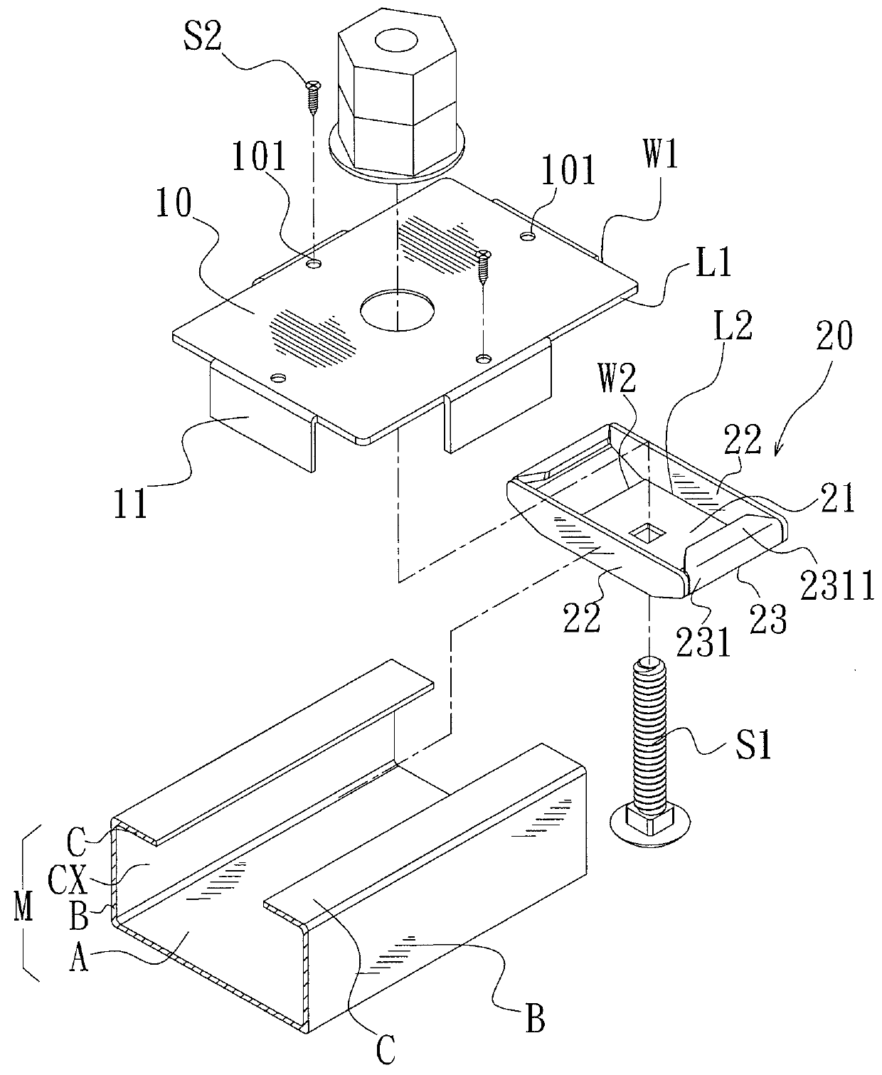
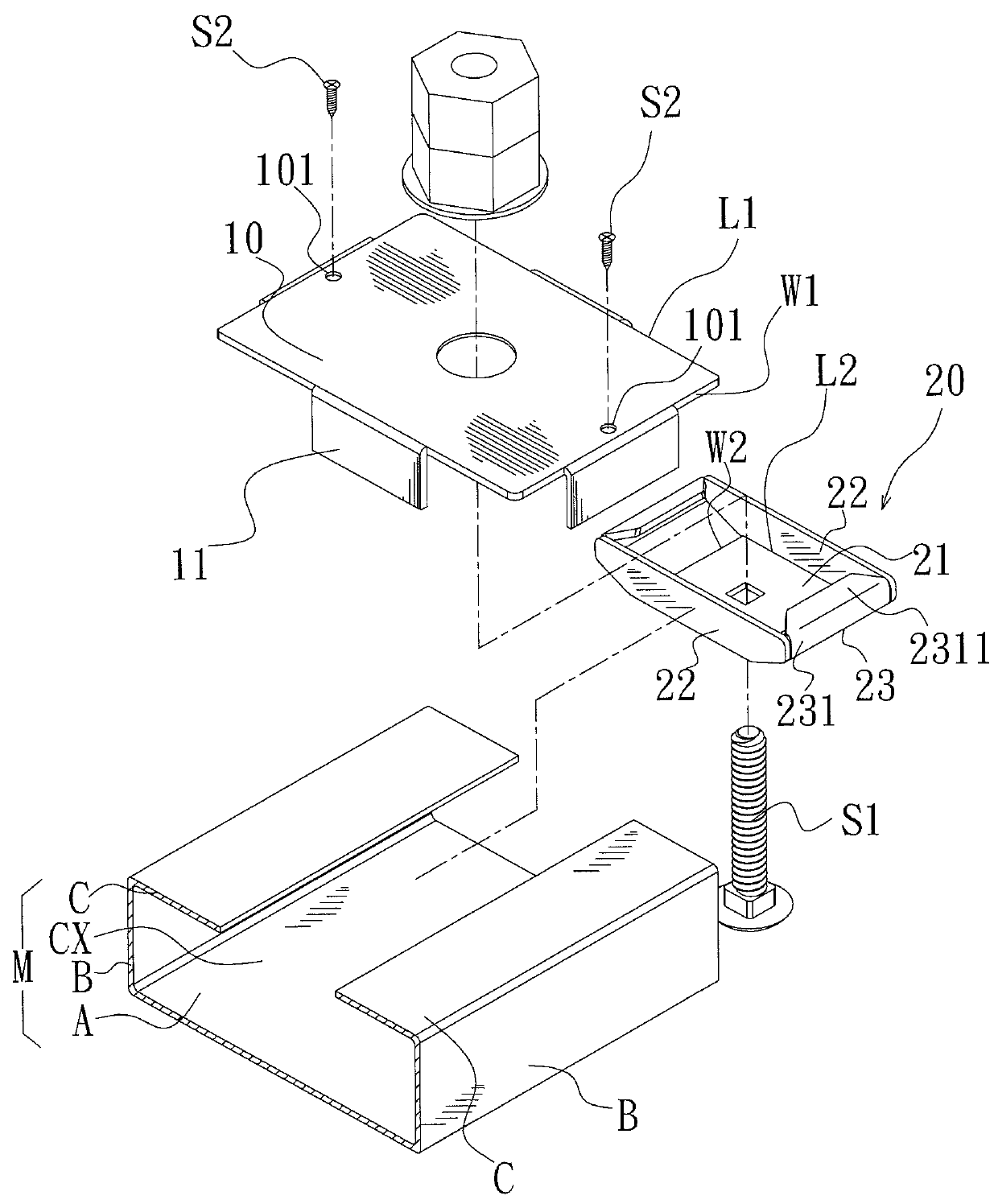
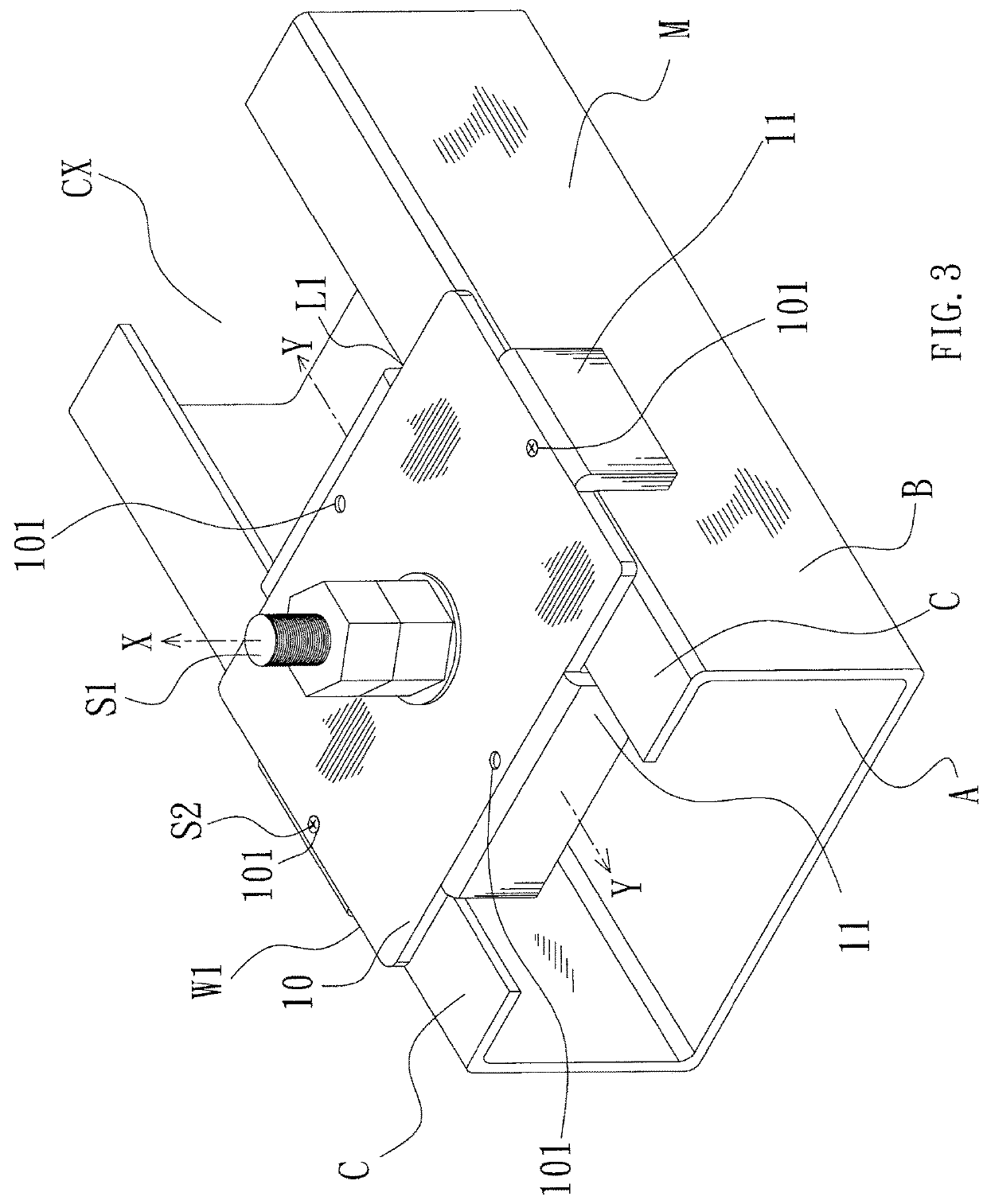
[0034]Referring to FIGS. 1-3; FIG. 1 is a three-dimensional exploded schematic view of a high-strength support assembly structure according to a first embodiment of the present invention, and shows pieces at openings of short sides of a fastening cover part being correspondingly fitted into opening sides of a C-type steel; FIG. 2 is a three-dimensional exploded schematic view of the high-strength support assembly structure according to the first embodiment of the present invention, and shows pieces at openings of long sides of the fastening cover part being correspondingly fitted into the opening sides of the C-type steel; FIG. 3 is a three-dimensional assembled schematic view of the high-...


PUM

PropertyMeasurementUnit
Lengthaaaaaaaaaa
Strengthaaaaaaaaaa

Abstract

The present invention discloses a high-strength support assembly structure, which utilizes a fastening cover part that can be slidably sleeved onto a C-type steel and an opening side thereof and a flexible internal stand; the flexible internal stand is placed inside of the C-type steel, and the internal stand and the fastening cover part are correspondingly fastened at the opening side of the C-type steel, such that the opening side of the C-type steel can serve as a connecting end or a bearing side. The present invention also discloses using or stacking a single or a plurality of connecting plates, so as to allow one C-type steel to be correspondingly joined to another C-type steel in order to expand a length thereof, or to adapt the C-type steel for serving as a corner.

Description

BACKGROUND OF THE INVENTIONa) Field of the Invention[0001]The present invention relates to a support assembly structure, and more particularly to a support assembly structure that is high-strength (resistant to deformation), highly versatile and easy to assemble.b) Description of the Prior Art[0002]The common support structures that are used for supporting solar panels, greenhouse farming sheds, parking sheds or even furniture stands are mostly three-dimensional rectangular supports (as indicated in FIG. 15) formed by using steel materials as transverse beams W and longitudinal beams L.[0003]The steel materials used as supports in the industry is divided into C-type steels, rectangular (round) tubes or H-type steels according to shapes of their cross sections; the C-type steels are most commonly used for setting up supports due to their high-strength, corrosion-resistance, ease of manufacturing and low costs.[0004]However, upon observation of current C-type steels used for setting u...

Claims


Application Information

Patent Timeline
IPC IPC(8): F24J2/52H02S20/23
CPCH02S20/23E04B2001/2415F24S25/13F24S25/00C22C38/00F16B7/187F24S2025/804F24S25/30F24S25/65F24S2025/6006H02S20/00Y02E10/50Y02E10/47Y02B10/10
Inventor DAI, PEI-LIN
Owner SONG PING SHANG
Why Eureka
Try Eureka