System and Method for Optical Sampling without an Optical Source

a technology of optical sampling and optical source, applied in the direction of non-linear optics, instruments, optics, etc., can solve the problems of inability to generate in practice, circuits come to their limits, and drastically increase the energy consumption, so as to achieve simple and fast adaptation of sampling to the signal-to-sample

Inactive Publication Date: 2018-09-20
SCHNEIDER THOMAS
View PDF0 Cites 1 Cited by
  • Summary
  • Abstract
  • Description
  • Claims
  • Application Information

AI Technical Summary

Benefits of technology

[0010]The frequency spacing between the comb lines defines the maximum real-time sampling rate. The overall bandwidth of the comb defines the maximum sampling rate for non-real-time sampling, or for a parallelization of the method. All required parameters can be tuned electrically, so that an adaptation of the sampling to the signal-to-sample is simple and fast.

Problems solved by technology

Since the data rates in the worldwide networks increase every year, these circuits come to their limits, which is expressed in a drastically increase of the energy consumption.
Due to causality, it cannot be generated in practice.
This leads to a distortion of the sampled signal, which has to be compensated by energy consuming electronics.
The higher the sampling rate, the higher is the energy consumption of electronic analog-to-digital converters.
Additionally, the analogue bandwidth of electronic samplers is restricted to a few 10th of GHz.
However the nonlinearities in the modulator, the balanced-receiver or the nonlinear element lead to a distortion of the sampled signal.
At the same time, mode-locked lasers are quite expensive and they hinder an integration of optical sampling on a chip together with the required electronics in order to build a complete analog-to-digital converter.

Method used


Image

  • System and Method for Optical Sampling without an Optical Source
  • System and Method for Optical Sampling without an Optical Source
  • System and Method for Optical Sampling without an Optical Source

Examples


Embodiment Construction

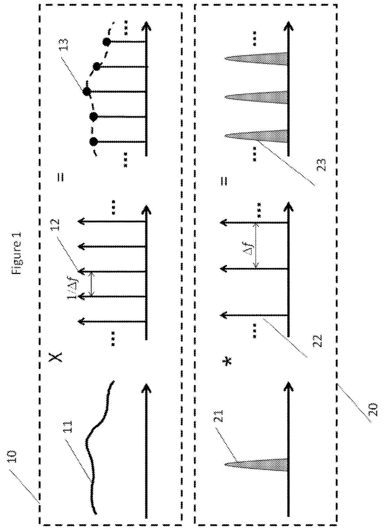
[0027]The method and system according to the present invention is based on the time-frequency duality described by Fourier analysis (described by FIGS. 1 and 2). An ideal sampling can be seen as the convolution between a signal spectrum ((21) in FIG. 1) and an unlimited frequency comb ((22) in FIG. 1). The result is an unlimited number of copies of the signal spectrum at the input of the sampling device (FIG. 1 (23)). In the time-domain this corresponds to a multiplication between the signal in the time-domain (FIG. 1 (11)) and a Dirac-Delta sequence (FIG. 1 (12)). The different pulses of the sequence are weighted with the amplitude value of the signal-to-sample (FIG. 1 (13)). According to the well-known Nyquist sampling theorem, to sample and restore a signal with a maximum frequency of fmax Hz properly, pulses with a minimum repetition rate of 2fmax should be utilized. This complies a sampling frequency of fs=2fmax=1 / ts, where ts is the time interval between two sampling points. T...


PUM

PropertyMeasurementUnit
spectrumaaaaaaaaaa
bias voltageaaaaaaaaaa
frequencyaaaaaaaaaa

Abstract

System and methods for the sampling of an optical signal by generating a plurality of copies of the spectrum of the said optical signal including at least one sampling block for the convolution between the optical input spectrum and an optical comb; wherein the said sampling block includes a modulator, and a bias voltage generator, the said sampling block is driven by an electrical comb generator and a phase shifter, the said electrical comb generator being configured to generate a number of N lines, with N from one to infinity, in the radio frequency domain, equally spaced in frequency and locked in phase, the said modulator being configured to generate a plurality of 2N+1 copies of the input spectrum from (i) the signal spectrum and (ii) a number of N lines provided by the said electrical comb generator.

Description

FIELD OF THE INVENTION[0001]The present invention relates to the sampling of optical or electrical signals. Since sampling is the first step to convert an analogue to a digital signal, the method is of special interest for test and measurement equipment, high-speed optical communications and wireless radar applications.BACKGROUND OF THE INVENTION[0002]During recent years, many efforts to increase the sampling rate and the effective number of bit (ENOB) of analogue-to-digital converters (ADC) have been made. Analogue-to-digital converters are required for the conversion of analogue into digital signals. These analogue signals can be wireless, like radar signals, they can be electrical, or optical signals. The network nodes of the internet for instance, require extensive analogue-to-digital conversion of coherent signals. The most common sampling method is a sampling with electronically sample-and-hold circuits. Since the data rates in the worldwide networks increase every year, these...

Claims


Application Information

Patent Timeline
Patent Type & Authority Applications(United States)
IPC IPC(8): G02F1/35G02F1/365
CPCG02F1/3532G02F2203/56G02F1/365
Inventor SCHNEIDER, THOMAS
Owner SCHNEIDER THOMAS
Why Eureka
Try Eureka