Wall lamp

Active Publication Date: 2018-10-18
DONGGUAN THAILIGHT SEMICON LIGHTING CO LTD
View PDF0 Cites 2 Cited by
  • Summary
  • Abstract
  • Description
  • Claims
  • Application Information

AI Technical Summary

Benefits of technology

[0016]Compared with the prior art, the beneficial effect of the present invention is that the main lens surface includes two planes inclined to the ground, and the light emitted by the

Problems solved by technology

Therefore, the light beam has a large scattering angle and cannot be effecti

Method used


Image

  • Wall lamp
  • Wall lamp
  • Wall lamp

Examples


Embodiment Construction

[0024]The present invention will be further described in conjunction with the drawings and the embodiments as below.

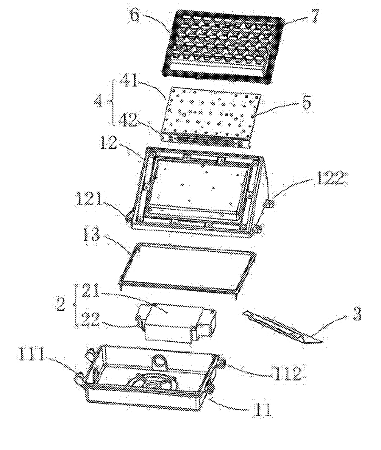
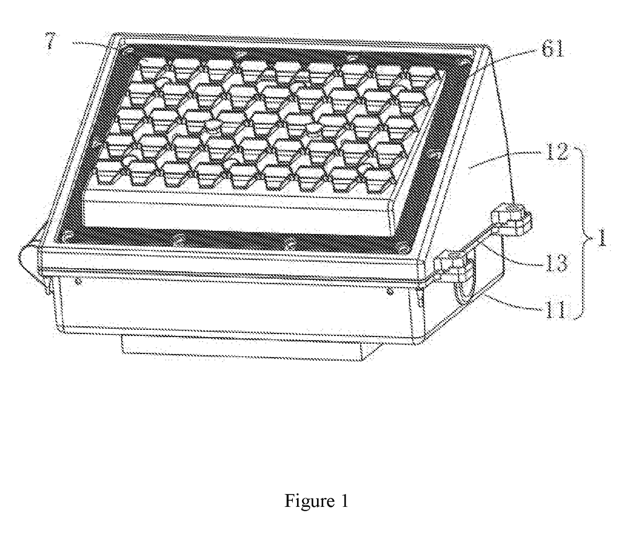
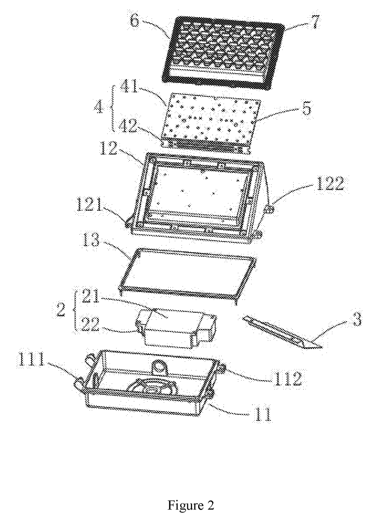
[0025]As shown in FIGS. 1-2, a wall lamp includes housing 1, power supply 2, bracket 3, substrate 4, a plurality of light-emitting units 5, lens board 6, and a plurality of lens units 7.

[0026]Housing 1 includes base 11 and top cover 12, and base 11 is fixedly connected to top cover 12. A chamber is formed between base 11 and top cover 12. As shown in FIG. 3 and FIG. 4, base 11 is a cuboid housing with an opening at one end, and top cover 12 is a right-angled triangular prism-shaped housing with an opening at one side. Base 11 includes two side lugs 112 and two pins 111. Two side lugs 112 are located on the same side of base 11 and are disposed opposite to two pins 111. Top cover 12 includes two pin holes 121 and two outer edges 122. Two outer edges 122 are located on the same side of top cover 12 and are arranged opposite to two pin holes 121. Each side lug 112 is prov...


PUM


Abstract

The invention discloses a wall lamp, including a plurality of light-emitting units, a lens board, and a plurality of lens units. The plurality of lens units are mounted on one side of the lens board, and a plurality of mounting grooves are provided on the other side. The plurality of mounting grooves are provided corresponding to the plurality of lens units for accommodating the light-emitting unit. The lens unit includes a main lens surface facing the light-emitting unit. The main lens surface including a first plane, the second plane and the third plane. The main lens surface includes two planes inclined to the ground, and the light emitted by the light-emitting units cooperating with the lens is projected to the ground under the action of the main lens surface, so that the light energy can be effectively utilized and saved.

Description

CROSS REFERENCE TO RELATED APPLICATIONS[0001]This application is based upon and claims priority to Chinese Patent Application No. 201720407458.8, filed on Apr. 18, 2017, the entire contents of which are incorporated herein by reference.TECHNICAL FIELD[0002]The present invention relates to a lighting appliance, particularly to a wall lamp.BACKGROUND[0003]The wall lamps are widely used in indoor and outdoor lighting and decoration as a commonly used lighting tool. The LED lamp featuring high efficiency, energy saving, safety, longevity, with compact design has become the main product in a new generation of lighting market and brings the rapid development of the industry of environmental protection and energy conservation. Most of the current wall lamps use flat-panel LED light group and converge light with a cone platform or hemispherical lens. Therefore, the light beam has a large scattering angle and cannot be effective converged, causing low light energy utilization and poor lighti...

Claims


Application Information

Patent Timeline
IPC IPC(8): F21V5/00F21S8/00F21V5/04F21V8/00
CPCF21V5/007F21S8/033G02B7/02G02B6/003F21Y2115/10F21V5/048F21Y2105/10G02B19/0028G02B19/0061
Inventor ZHOU, WENBO
Owner DONGGUAN THAILIGHT SEMICON LIGHTING CO LTD
Why Eureka
Try Eureka