Optical fiber deviation corrector

A technology of a deviation corrector and optical fiber, applied in the field of optical fiber deviation corrector, can solve the problems of waste of light energy, inability to accurately calculate the small movement of parts, offset or defect size, and limited detection accuracy.

Pending Publication Date: 2017-11-24
陈郁芝 +4
View PDF10 Cites 1 Cited by
  • Summary
  • Abstract
  • Description
  • Claims
  • Application Information

AI Technical Summary

Problems solved by technology

[0004] The main purpose of the present invention is to propose a kind of optical fiber correcting device, aiming at solving the optical energy waste caused by the existing optical correcting device in the prior art, and when detecting the parts to be tested, the accuracy of the optical correcting device is affected. Limited to the size and spacing of the photoelectric conversion units on the photoelectric converter, the detection accuracy is limited, and technical problems such as the small movement, offset or defect size of the part cannot be accurately calculated

Method used


Image

  • Optical fiber deviation corrector
  • Optical fiber deviation corrector
  • Optical fiber deviation corrector

Examples


Embodiment Construction

[0023] In order to make the purpose, features and advantages of the present invention more obvious and understandable, the technical solutions in the embodiments of the present invention will be clearly and completely described below in conjunction with the accompanying drawings in the embodiments of the present invention. Obviously, the described The embodiments are only some of the embodiments of the present invention, but not all of them. Based on the embodiments of the present invention, all other embodiments obtained by those skilled in the art without making creative efforts belong to the protection scope of the present invention.

[0024] In order to illustrate the technical solutions of the present invention, specific examples are used below to illustrate.

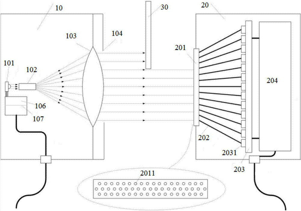
[0025] For a better understanding of the invention, please refer to figure 1 Shown is a schematic structural view of an optical fiber correction device, which includes: a parallel light transmitter 10 and a parall...


PUM


Abstract

The invention discloses an optical fiber deviation corrector. The optical fiber deviation corrector comprises a parallel light emitter and a parallel light receiving detector. The parallel light emitter comprises a laser emitter, an angle modulation device, a parallel light control lens component and a light spot limiting diaphragm. The parallel light receiving detector comprises an optical fiber pixel point integration plate, transmission optical fibers, a photoelectrical converter and a signal acquiring and processing device. The angle modulation device modulates a laser beam into preset-angle divergent light, the parallel light control lens component modulates the divergent light into parallel light, the light spot limiting diaphragm modulates the parallel light into parallel light spots as large as the optical fiber pixel point integration plate, the parallel light spots is emitted to the optical fiber pixel point integration plate and acquired by the same to obtain optical signals, the optical signals are transmitted to the photoelectrical converter through the transmission optical fibers and converted into electrical signals by the photoelectrical converter, and the electrical signals are transmitted to the signal acquiring and processing device. The optical fiber deviation corrector has advantages that light energy is saved, detection accuracy is improved, and minor deviation or defect sizes of parts can be calculated accurately.

Description

technical field [0001] The invention belongs to the technical field of optical devices, in particular to an optical fiber deviation corrector. Background technique [0002] In the prior art, when the optical rectifier is working, the monochromatic laser light source of the optical rectifier emits a laser beam to the parallel light control lens, but when emitting the laser beam, because the divergence angle of the laser beam is not limited, the laser beam will form a The area of ​​the light field is larger than the area of ​​the parallel light control lens, resulting in a waste of light energy. In addition, when testing the parts to be tested, the accuracy of the optical rectifier is limited by the size and spacing of the photoelectric conversion units on the photoelectric converter. The precision is limited, and it is impossible to accurately calculate the small movement of the part, the offset, or the size of the defect. [0003] Therefore, in the prior art, there is an op...

Claims


Application Information

Patent Timeline
Patent Type & Authority Applications(China)
IPC IPC(8): G01D5/353
CPCG01D5/35338
Inventor 陈郁芝李学金周华胜耿优福洪学明
Owner 陈郁芝
Why Eureka
Try Eureka