Drive control method of drive stage device

a technology of drive stage and control method, which is applied in the direction of mechanical measuring arrangement, instruments, and using mechanical means, etc., can solve the problems of damage to the internal mechanism of the rotary table, degrade the shape measurement, and natural inability to guarantee accuracy

Active Publication Date: 2018-10-18
MITUTOYO CORP
View PDF0 Cites 10 Cited by
  • Summary
  • Abstract
  • Description
  • Claims
  • Application Information

AI Technical Summary

Benefits of technology

[0008]An advantage of the present invention is to provide a control method of a drive stage device that is capable of achieving drive control appropriate to a weight or the like of an object resting on a stage of the device.
[0009]A control method of a drive stage device according to an aspect of the present invention includes: causing a stage to float on an air bearing; measuring, as a first height, a height of the stage while floating on the air bearing; placing a work piece on the stage; measuring, as a second height, a height of the stage when the stage is holding the work piece; calculating, as a drop amount, a difference between the first height and the second height; calculating a weight of the work piece based on the drop amount; determining an upper limit speed of one of rotational drive and horizontal movement of the stage based on the calculated work piece weight; and controlling a speed of the one of the rotational drive and the horizontal movement of the stage so as to not exceed the upper limit speed.
[0010]A control method of a drive stage device according to another aspect of the present invention includes: causing a stage to float on an air bearing; measuring, as a first height, a height of the stage while floating on the air bearing; placing a work piece on the stage; measuring, as a second height, a height of the stage when the stage is carrying the work piece; calculating, as a drop amount, a difference between the first height and the second height; calculating a weight of the work piece based on the drop amount; determining one of an acceleration speed limit and a deceleration speed limit of one of rotational drive and horizontal movement of the stage based on the calculated work piece weight; and controlling the one of the acceleration speed and the deceleration speed of the one of the rotational drive and the horizontal movement of the stage so as to not exceed the limit.
[0011]According to another aspect of the present invention, preferably, the calculated weight of the work piece is compared with a maximum load capacity of the drive stage device, and when the calculated weight of the work piece exceeds the maximum load capacity, a user is notified.
[0012]A control method of a shape measuring device according to another aspect of the present invention is a control method of a shape measuring device provided with a rotary table device having a rotary table that rotates while carrying a work piece, and a coordinate measurer detecting a surface of the work piece and measuring a shape of the work piece, the control method including: causing the rotary table to float on an air bearing; measuring, as a first height, a height of the rotary table while floating on the air bearing; placing the work piece on the rotary table; measuring, as a second height, a height of the rotary table when the rotary table is carrying the work piece; calculating, as a drop amount, a difference between the first height and the second height; calculating a weight of the work piece based on the drop amount; determining an upper limit of a rotation speed of the rotary table based on the calculated work piece weight; and measuring, with the coordinate measurer, the shape of the work piece resting on the rotary table while controlling the rotation speed of the rotary table so as to not exceed the upper limit.
[0013]A control method of a shape measuring device according to another aspect of the present invention is a control method of a shape measuring device provided with a rotary table device having a rotary table that rotates while carrying a work piece, and a coordinate measurer detecting a surface of the work piece and measuring a shape of the work piece, the control method including: causing the rotary table to float on an air bearing; measuring, as a first height, a height of the rotary table while floating on the air bearing; placing the work piece on the rotary table; measuring, as a second height, a height of the rotary table when the rotary table is carrying the work piece; calculating, as a drop amount, a difference between the first height and the second height; calculating a weight of the work piece based on the drop amount; determining one of an acceleration speed limit and a deceleration speed limit of rotation of the rotary table based on the calculated work piece weight; and measuring, with the coordinate measurer, the shape of the work piece resting on the rotary table while controlling the one of the acceleration speed and the deceleration speed of the rotation of the rotary table so as to not exceed the limit.

Problems solved by technology

Any aberration in the rotation of the rotary table will, of course, degrade the shape measurement results.
When the rotary table is driven while holding a work piece that exceeds the load capacity, the rotation accuracy naturally cannot be guaranteed, and such operation may damage internal mechanisms of the rotary table.
However, mistaken operation does frequently occur in which a work piece exceeding the load capacity is measured by the roundness measuring device.

Method used


Image

  • Drive control method of drive stage device
  • Drive control method of drive stage device
  • Drive control method of drive stage device

Examples


first embodiment

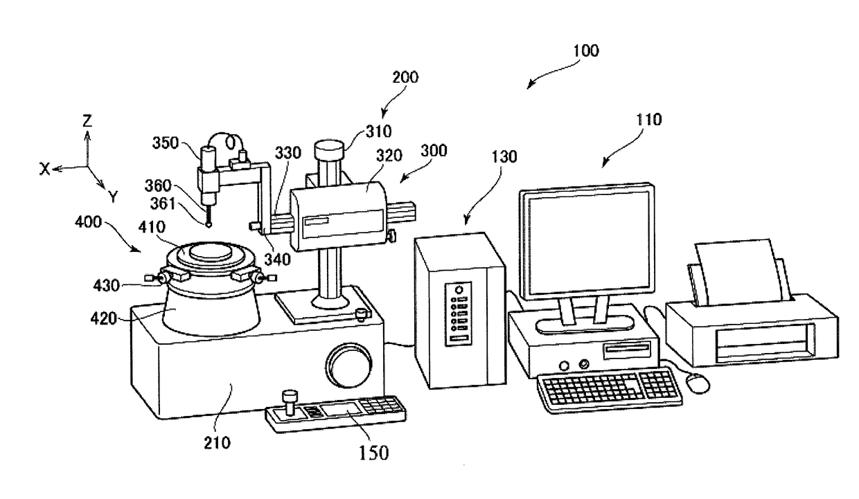
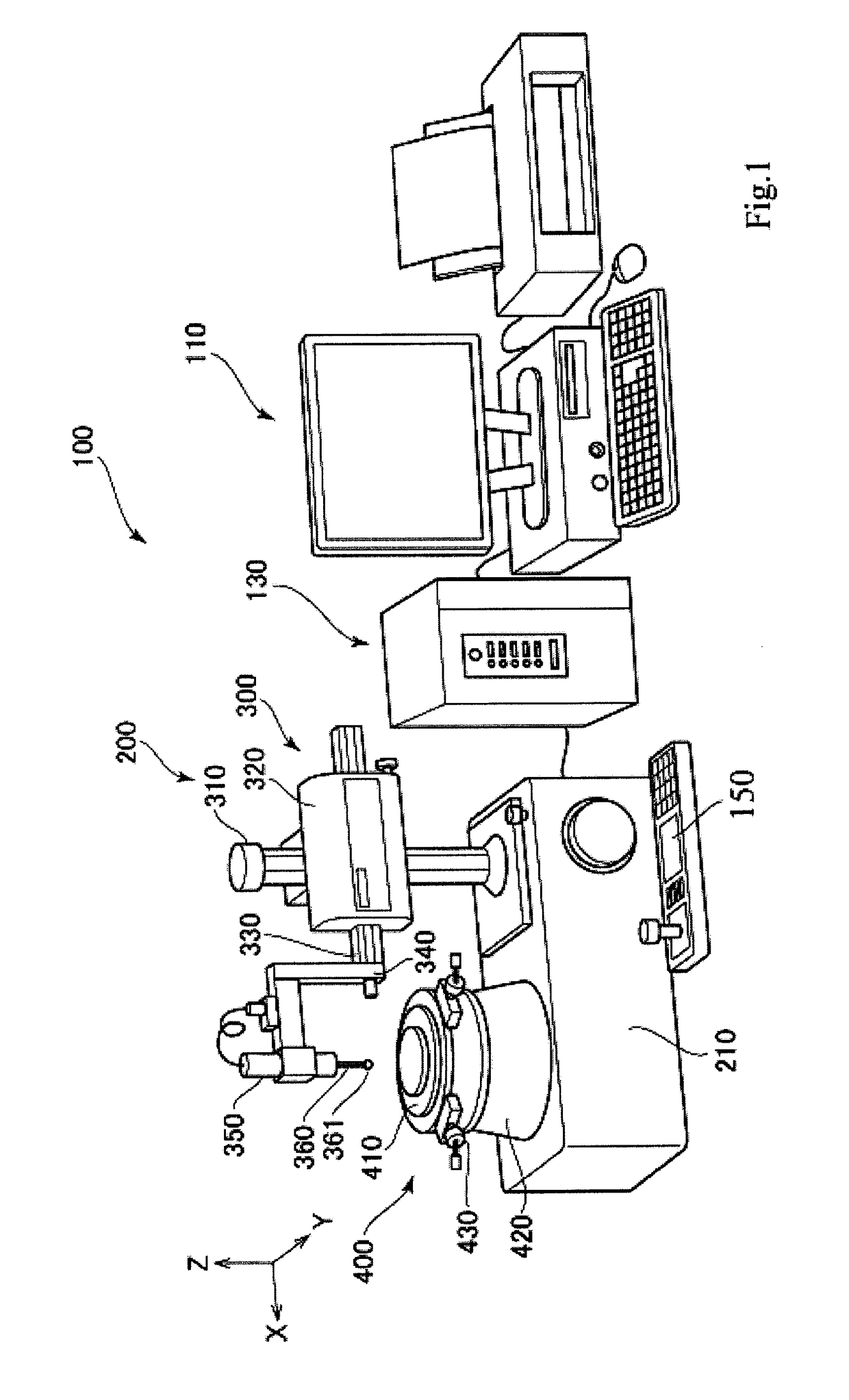
[0033]FIG. 1 is an external view of a roundness measuring device. A roundness measuring device 100 includes a measurer main body 200, a motion controller 130, a host computer 110, and a console 150.

[0034]The measurer main body 200 includes a stand 210, a coordinate measurer 300, and a rotary table device 400.

[0035]The coordinate measurer 300 includes a Z axis column 310, a Z slider 320, an X arm 330, a head holder 340, and a probe head 350. The Z axis column 310 stands upright on the stand 210, parallel to a Z axis. The Z slider 320 is provided to the Z axis column 310 so as to be capable of displacement in a Z direction (up-down direction). The X arm 330 is supported on the Z slider 320 so as to be capable of advancing and retreating in an X direction. The head holder 340 is an “L” shaped member, the base end of which is attached to a forefront end of the X arm 330. The probe head 350 is attached to a forefront end of the head holder 340. The probe head 350 is a lever-type electric...

first modification

[0059]In the embodiment described above, the work piece weight is calculated from the drop amount D of the rotary table 410, and a rotation speed and acceleration / deceleration speed that correspond to the work piece weight are found as limit values. In an exemplary modification, a rotation speed and acceleration / deceleration speed that correspond to a moment of inertia Iw of the work piece W may be found as the limit values. For example, as illustrated in FIG. 12, a diameter (for example, a maximum diameter) of the work piece W is measured ahead of time, then the moment of inertia Iw of the work piece W is roughly calculated using the measured diameter and the weight of the work piece W calculated as described in the embodiment above. Then limit values of the rotation speed and acceleration / deceleration speed are set in accordance with the calculated moment of inertia Iw. (For example, in FIGS. 10 and 11, the work piece weight may be read as the moment of inertia.)

[0060]Moreover, th...

second modification

[0061]In the description of the embodiment given above, the coordinate measurer 300 is installed in the measuring device (roundness measuring device). Therefore, the drop amount of the rotary table is detected (measured) using a measurement operation of the coordinate measurer 300. However, a measuring apparatus that measures the drop amount of the rotary table separately from the measurement operation of the coordinate measurer may be added to the rotary table device. For example, a strain gage or scale may be incorporated into the rotary table device and detect the drop amount of the rotary table. However, because a feature of the present invention is to appropriately control the drive speed of the rotary table, the work piece weight does not need to be detected with a high degree of accuracy. Detection accuracy of the work piece weight may be in units of kilograms or tens of kilograms, for example. Therefore, rather than providing a separate, specialized weight sensor, a coordina...


PUM


Abstract

In a control method of a drive stage device, a stage is floated on an air bearing, then a height of the stage while floating on the air bearing is measured as a first height. A work piece is placed on the stage and a height of the stage while holding the work piece is measured as a second height. A difference between the first height and the second height is calculated as a drop amount, and a weight of the work piece is calculated based on the drop amount. An upper limit speed of one of rotational drive and horizontal movement of the stage is determined based on the calculated work piece weight. A speed of the one of the rotational drive and the horizontal movement of the stage is controlled so as to not exceed the upper limit speed.

Description

CROSS-REFERENCE TO RELATED APPLICATIONS[0001]The present application claims priority under 35 U.S.C. § 119 of Japanese Application No. 2017-081986, filed on Apr. 18, 2017, the disclosure of which is expressly incorporated by reference herein in its entirety.BACKGROUND OF THE INVENTION1. Field of the Invention[0002]The present invention relates to a drive control method of a drive stage device and, as an example, relates to a drive control method of a rotary table.2. Description of Related Art[0003]A roundness measuring device is a known example of a shape measuring device (Japanese Patent No. 3,949,910). The roundness measuring device includes a rotation mechanism and closely measures changes in the radius of a measured object (hereafter referred to as “work piece”) having a round shape. The measurement accuracy of the roundness measuring device is closely related to the rotation accuracy of a rotary table.[0004]Any aberration in the rotation of the rotary table will, of course, deg...

Claims


Application Information

Patent Timeline
Patent Type & Authority Applications(United States)
IPC IPC(8): G01B5/20G01B5/00G01B5/008G01B5/06G01G5/02
CPCG01B5/201G01B5/0004G01B5/008G01B5/061G01G5/02G01B21/20G05D13/62G01G19/083
Inventor HONDA, HIROOMIKANEMATSU, TOSHIHIRO
Owner MITUTOYO CORP
Why Eureka
Try Eureka