
Sandwich diamond-like carbon overcoat for use in slider designs of proximity recording heads

a proximity recording head and diamond-like carbon technology, applied in the direction of maintaining the head carrier alignment, recording information storage, instruments, etc., can solve the problems of material loss from both magnetic storage disk and abs, material loss forms debris, and the ability of the proximity recording head to register binary data on the magnetic storage disk suffers a significant degradation

Inactive Publication Date: 2005-10-18
WESTERN DIGITAL TECH INC
View PDF12 Cites 49 Cited by
  • Summary
  • Abstract
  • Description
  • Claims
  • Application Information

AI Technical Summary

Problems solved by technology

Because of the surface contact with the magnetic storage disk made by the trailing edge region of the ABS, the surfaces of the magnetic storage disk and the ABS of the conventional slider experience a continual erosion or wear, thereby resulting in material loss from both the magnetic storage disk and the ABS.
This material loss forms debris in the vicinity of the pole tip region of the read / write sensor.
As the debris accumulates, the ability of the proximity recording head to register binary data onto the magnetic storage disk suffers a significant degradation due to an increase in spacing between the pole tip and the surface of the magnetic storage disk.
If the wear were not properly controlled, the burnishing would eventually expose the GMR read / write sensor to the ambient.
Because of its susceptibility to atmospheric corrosion, the GMR read / write sensor may fail to achieve its functionality and proximity recording performance when exposed to the drive environment.
While the conventional two-layer DLC pad may have in theory provided a satisfactory resolution of the foregoing concern, in practice it does have a serious deficiency that likely renders the goal of proximity recording unattainable.
This deficiency lies in the fact that due to manufacturing tolerances, there exists a small deviation in the design flying height of the slider, which herein is referred to as sigma.
The flying height sigma translates into a distribution of interference height, resulting in some sliders exposing to larger interference heights than others.
Consequently, this presents a number of challenging problems to the conventional DLC pad.
Because the E-DLC layer of the conventional DLC pad would experience a varying degree of burnishing due to the flying height sigma, the proximity recording heads employing the conventional DLC pads thus cannot in general achieve uniform steady state clearance or magnetic spacing, thereby leading to a varying performance of such proximity recording heads.
Moreover, the inability to cope with the distribution of flying height sigma also increases the risk of a potential excessive wear of the E-DLC layer of the conventional contact DLC pad when the slider is flying closer to the magnetic disk surface than the average flying height.
In some instances, the wear of the conventional contact DLC pad is so extensive that allows the read / write sensor to be exposed to the corrosive environment in which the proximity recording head operates.
Once exposed, the read / write sensor becomes oxidized or corroded quite rapidly, thereby resulting in damage to the proximity recording head and consequently causing catastrophic failure of the magnetic disk drive.
In light of unresolved concerns with the conventional DLC protective pad employed in proximity recording applications, it is realized that there is an unfulfilled need for an improved DLC pad design for proximity recording that addresses the problems associated with the flying height sigma variation of the sliders in the proximity recording heads.

Method used


Image

  • Sandwich diamond-like carbon overcoat for use in slider designs of proximity recording heads
  • Sandwich diamond-like carbon overcoat for use in slider designs of proximity recording heads
  • Sandwich diamond-like carbon overcoat for use in slider designs of proximity recording heads

Examples


Embodiment Construction

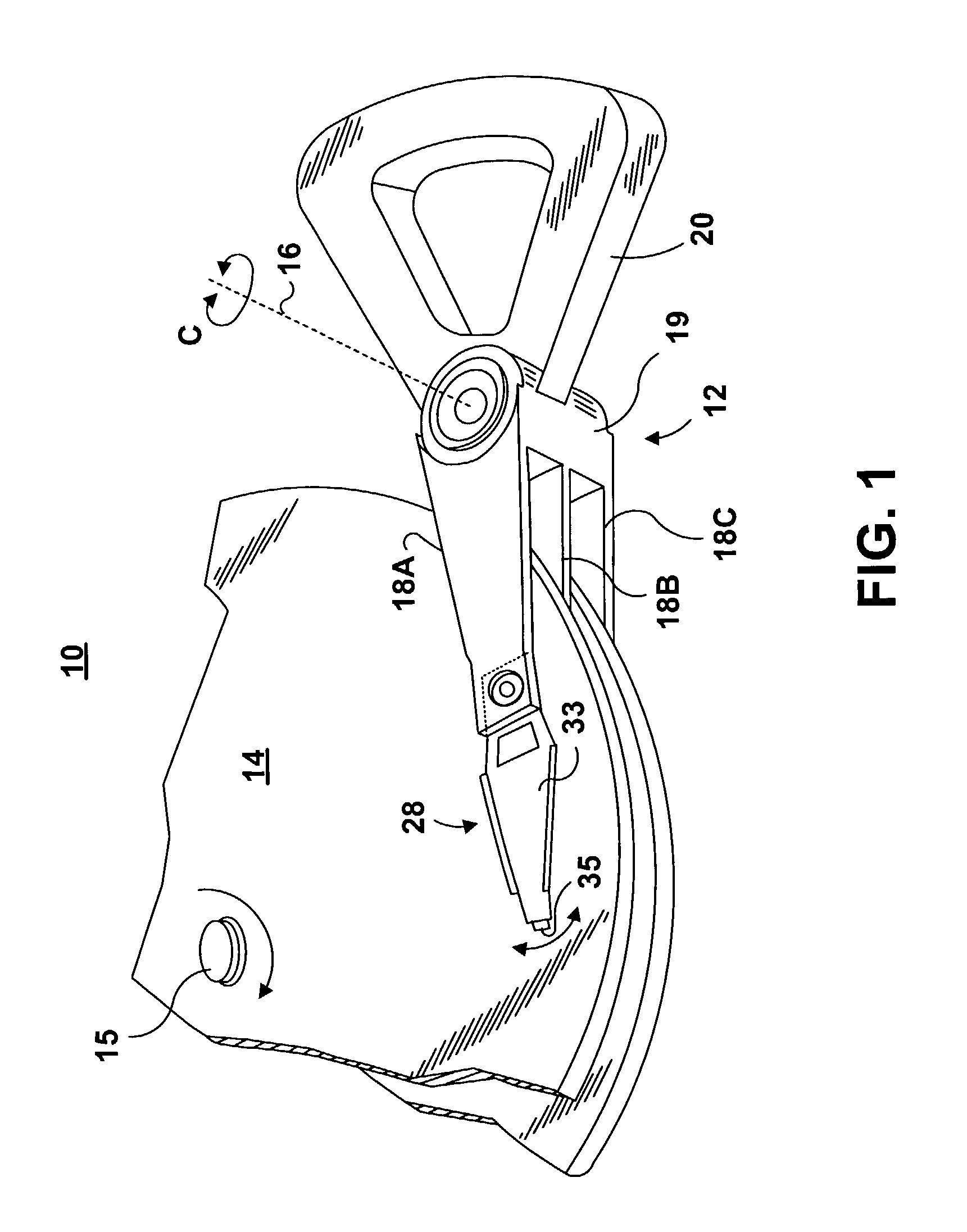
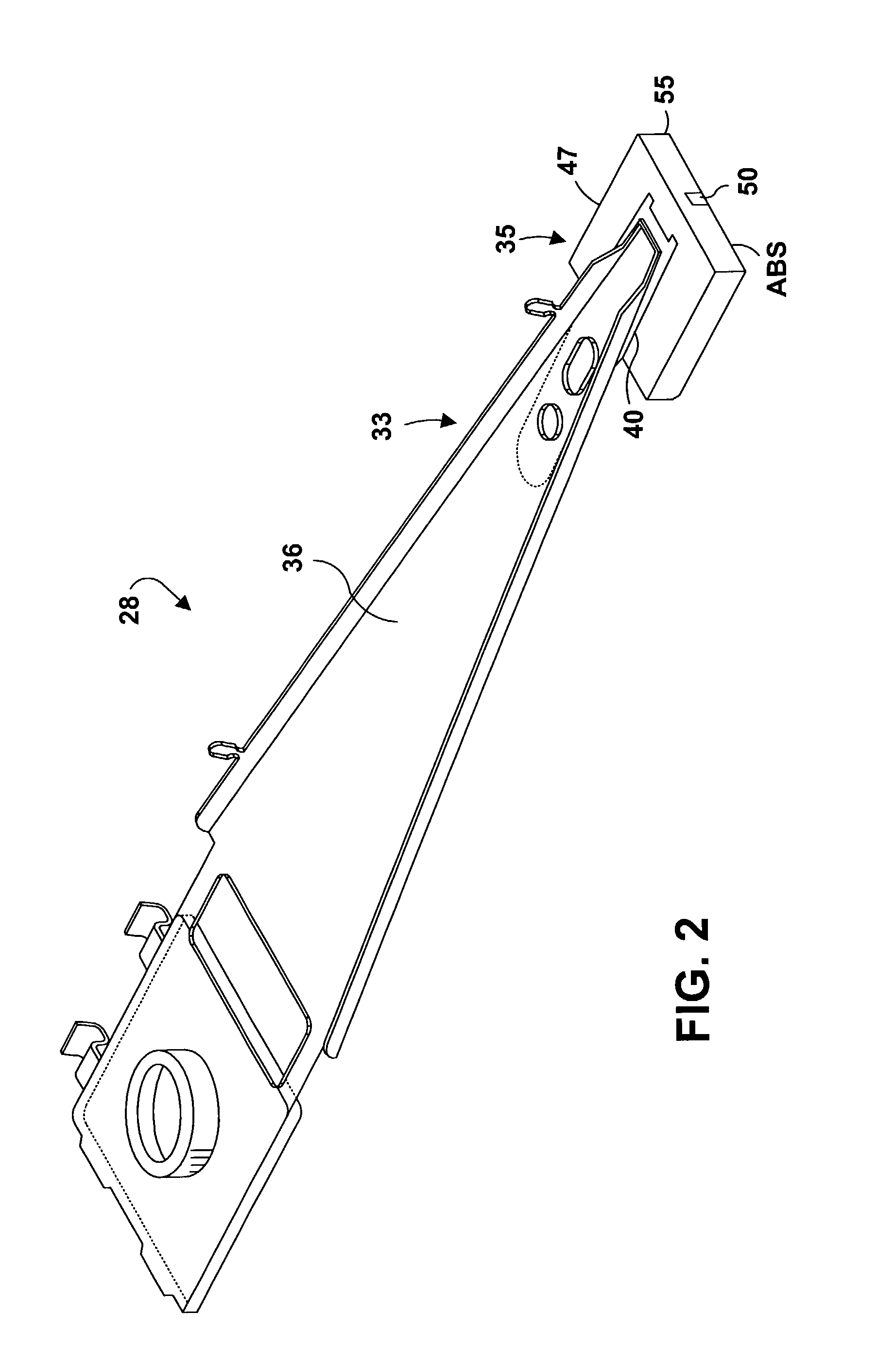
[0030]FIG. 1 illustrates a disk drive 10 comprised of a head stack assembly 12 and a stack of spaced apart smooth media magnetic data storage disks or smooth media 14 that are rotatable about a common shaft 15. The head stack assembly 12 is rotatable about an actuator axis 16 in the direction of the arrow C. The head stack assembly 12 includes a number of actuator arms, only three of which 18A, 18B, 18C are illustrated, which extend into spacings between the disks 14.

[0031]The head stack assembly 12 further includes an E-shaped block 19 and a magnetic rotor 20 attached to the block 19 in a position diametrically opposite to the actuator arms 18A, 18B, 18C. The rotor 20 cooperates with a stator (not shown) for rotating in an arc about the actuator axis 16. Energizing a coil of the rotor 20 with a direct current in one polarity or the reverse polarity causes the head stack assembly 12, including the actuator arms 18A, 18B, 18C, to rotate about the actuator axis 16 in a direction subst...


PUM


Abstract

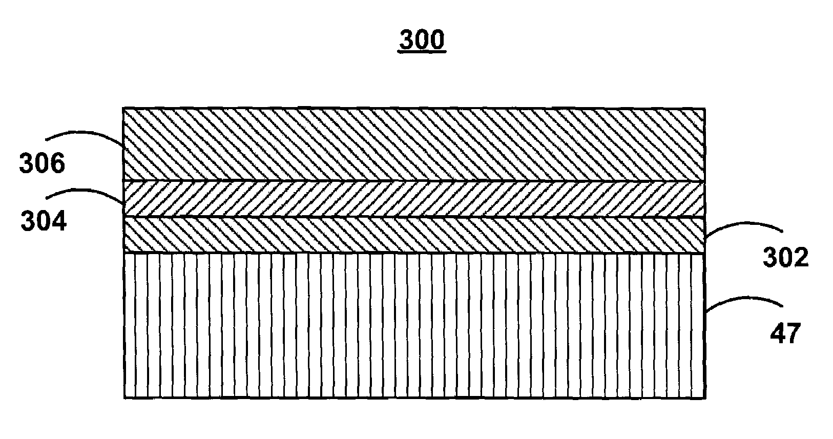
A slider is formed of an air bearing surface coated with a wear limiting coating that substantially limits surface wear of the air bearing surface encountered in proximity recording. The wear limiting coating is comprised of a wear inhibiting layer formed on the air bearing surface and a sacrificial layer formed on the wear inhibiting layer. The two coatings of the wear limiting coating have different mechanical properties so that the sacrificial layer is burnished, exposing the wear inhibiting layer. This design substantially limits the surface wear of the air bearing surface typically encountered in proximity recording, resulting in less debris accumulation, which could otherwise adversely affect the performance of the proximity recording head. This self-limiting burnishing action overcomes the flying height variation due to manufacturing tolerances and provides extremely small and uniform magnetic spacing, which greatly enhances the proximity recording. Moreover, the burnishing action also achieves an improved flying stability and a reduction in the altitude sensitivity.

Description

CROSS-REFERENCE TO RELATED APPLICATION[0001]The present application is related to co-pending U.S. patent application Ser. No. 10 / 223,922, titled “Proximity Recording Air Bearing Design for a Data Storage System,” which is assigned to the same assignee as the present application, and which is incorporated herein by reference in its entirety.FIELD OF INVENTION[0002]The present invention relates in general to data storage systems such as disk drives, and it particularly relates to a thin film read / write head for use in such data storage systems. More specifically, the present invention provides a new sandwich layer of diamond-like carbon (DLC) overcoat for use in slider designs of proximity recording heads. The DLC layer design substantially limits the surface wear of the air bearing surface typically encountered in proximity recording, resulting in less debris accumulation which would otherwise adversely affect the performance of the proximity recording head.BACKGROUND OF THE INVENTIO...

Claims


Application Information

Patent Timeline
IPC IPC(8): G11B5/60
CPCG11B5/6005G11B5/3106G11B5/6082
Inventor KULKARNI, ASHOK VENKATESHPRABHAKARAN, VIJAYLEVI, PABLO GABRIELSUN, BIAOSLADEK, ERIC THOMASSULLIVAN, MICHAEL THOMAS
Owner WESTERN DIGITAL TECH INC
Learn More