Magnetic head suspension assembly fabricated with integral load beam and flexure
What is AI technical title?
AI technical title is built by PatSnap AI team. It summarizes the technical point description of the patent document.
a technology of load beam and flexure, applied in the direction of magnetic recording, instruments, data recording, etc., can solve the problems of weak pitch, roll and bending stiffness, and achieve the effect of reducing z-heigh
Inactive Publication Date: 2008-04-01
WESTERN DIGITAL TECH INC
View PDF32 Cites 50 Cited by
Summary
Abstract
Description
Claims
Application Information
AI Technical Summary
This helps you quickly interpret patents by identifying the three key elements:
Problems solved by technology
Method used
Benefits of technology
Benefits of technology
[0008]An object of this invention is to provide a head suspension and slider assembly having significantly reduced Z-height.
[0009]Another object of this invention is to provide a head suspension assembly characterized by low pitch and roll stiffness.
[0010]Another object is to provide a head suspension assembly characterized by low bending stiffness with decreased gram load tolerance effects.
[0012]A further object is to provide a head suspension design that affords significant savings and advantages in manufacture and mass production.
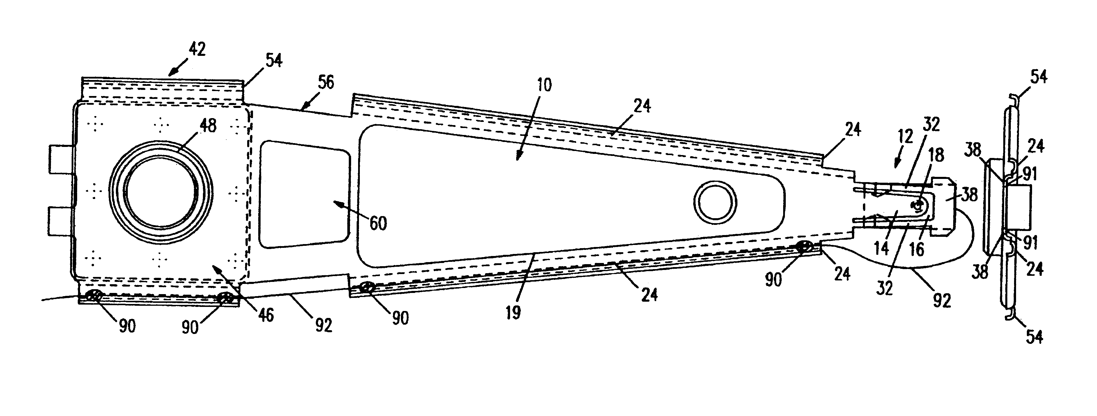
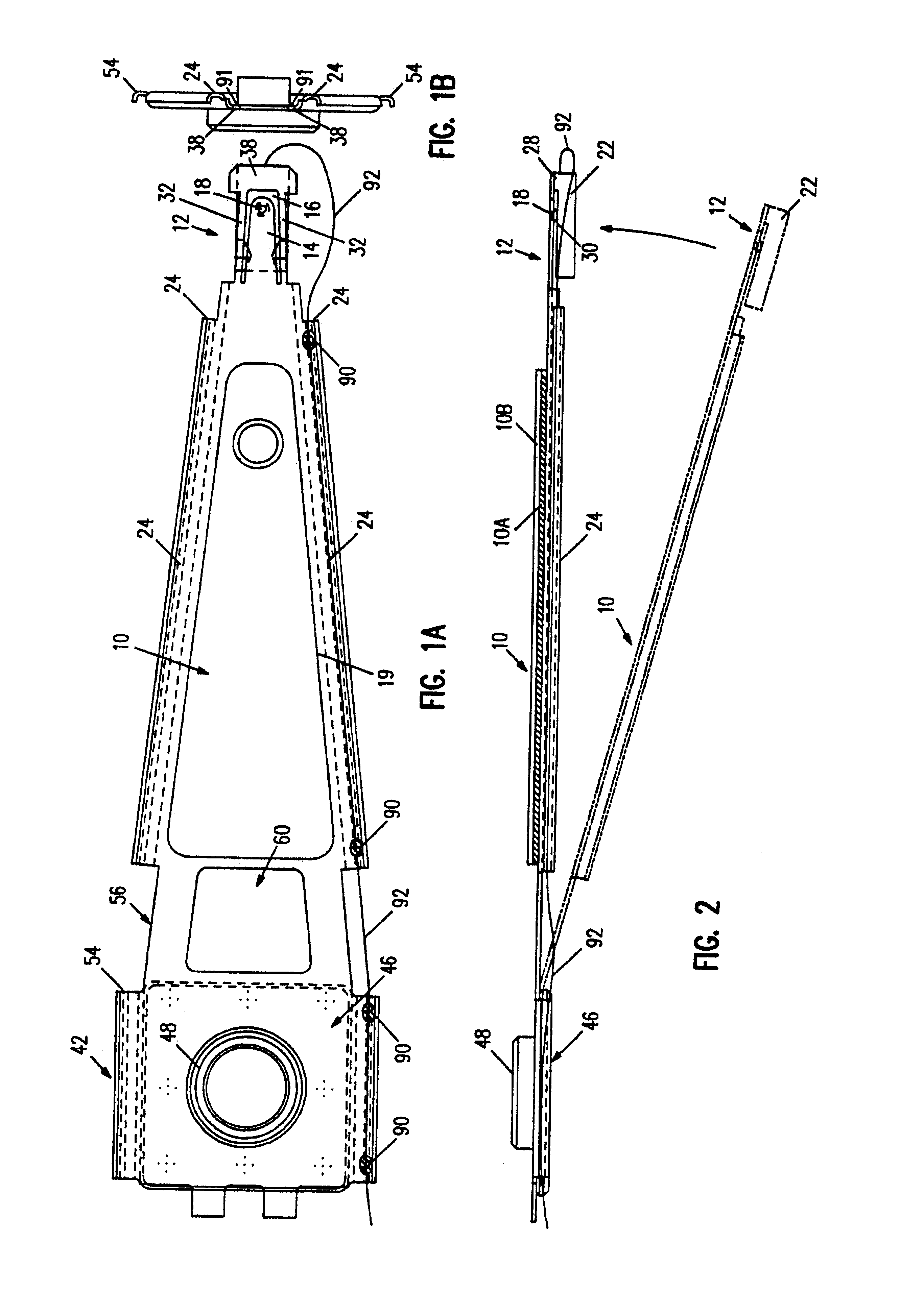
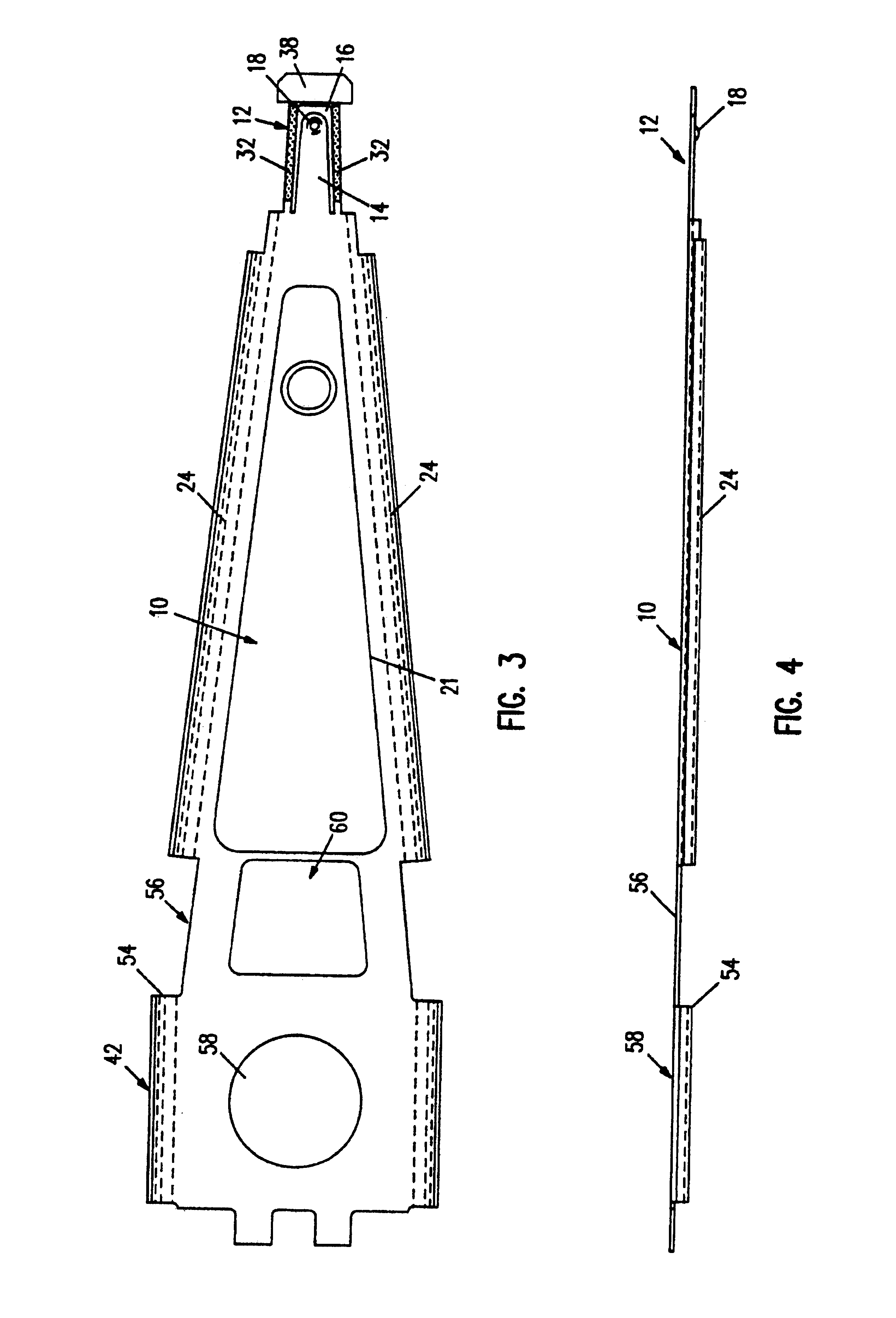
[0013]According to this invention, a magnetic head suspension assembly is formed from an integral planar piece comprising a load beam section and flexure section. The load beam is configured preferably as a truncated conical section having flanges along its sides and an extending tongue at its narrow end. The side flanges are formed with U-shaped channels and provide rigidity and stiffness to the load beam section. The load beam tongue extends into the flexure section and is formed with a hemispherical load dimple which faces down to the non-air bearing surface of a head slider. A U-shaped cutout portion that is formed in the flexure section adjacent to the load beam tongue delineates the shape of the tongue. In one embodiment of the invention, the flexure section includes two narrow etched legs that extend from the load beam and are disposed adjacent to the cutout portion. The narrow legs are connected by a lateral ear at the end of the flexure.from the narrow end of the load beam section into a shaped opening of the flexure section. The load beam tongue is formed with a load supporting protrusion or dimple that extends downward to contact a non-air bearing surface of a head slider. The shaped opening defines two flexure beams that extend in a longitudinal direction of the load beam. The flexure beams are connected by a transverse section at the end of the flexure section opposite the narrow end of the load beam section. <?insert-end id="INS-S-00007" ?>In this implementation, the head slider is bonded to the bottom surface of the lateral ear.transverse section. In an alternative embodiment, the flexure section includes outriggers configured as a split tongue to which the slider is bonded.
Problems solved by technology
These suspensions are characterized by weak pitch, roll and bending stiffness when the head is flying over the disk surface.
Method used
Image
Click on the blue label to locate the original text in one second.
Reading with bidirectional positioning of images and text.
Examples
Embodiment Construction
[0037]With reference to FIGS. 1A-5B, a magnetic head suspension assembly includes a load beam section 10, a flexure section 12, a leaf spring section 56 and a rear mount section 42. The suspension is formed from an integral flat piece of nonmagnetic material, preferably a 300 Series type stainless steel having a thickness of about 0.0012 to 0.0015 inch. As a result of using an integral piece, the load beam section 10 and flexure section 12, as well as the leaf spring section 56 and rear mount section 42, are disposed substantially in a single plane. No separate forming of individual load beam and flexure parts is required. Therefore, no assembly steps of joining and welding are needed for attaching the flexure to the load beam.
[0038]The load beam section 10 is preferably made in a truncated conical or triangular shape. The load beam section has a short tapered tongue 14 extending from its relatively narrow end into the flexure section 12. The tongue 14 is delineated by a U-shaped cu...
PUM
Property
Measurement
Unit
thick
aaaaa
aaaaa
thick
aaaaa
aaaaa
distance
aaaaa
aaaaa
Abstract
A magnetic head suspension assembly is fabricated with an integral piece which includes a load beam section, a flexure section, a rear mount section and a leaf spring section between the load beam and rear mount. A tongue extends from the load beam to the flexure and has a down-facing load dimple which contacts the non-air bearing surface of an attached air bearing slider. The flexure includes narrow thin legs adjacent to a cutout that delineates the load beam tongue. The head suspension is characterized by a high first bending mode frequency and low pitch and roll stiffness.
Description
[0001]ThisThe present application is a divisional application of application Ser. No. 08 / 521,786 filed Aug. 31, 1995, now abandoned, which is a reissue of application Ser. No. 08 / 042,906 filed Apr. 5, 1993, which issued as U.S. Pat. No. 5,282,103 on Jan. 25, 1994, which is a continuation-in-part of application Ser. No. 07 / 958,516, filed Oct. 7, 1992, now abandoned. The present application is related to reissue application Ser. Nos. 08 / 662,531 and 08 / 662,528 now U.S. Pat. RE39478, issued on Jan. 23, 2007, both filed Jun. 13, 1996, and also to copending reissue application Ser. No. 10 / 631,993 filed Jul. 30, 2003.CROSS-REFERENCE TO COPENDING APPLICATION[0002]Copending U.S. patent application Ser. No. 07 / 926,033 filed Aug. 5, 1992<?insert-start id="INS-S-00004" date="20080401" ?>, now U.S. Pat. No. 5,299,081 issued on Mar. 29, 1994, <?insert-end id="INS-S-00004" ?>is directed to a head suspension assembly particularly useful with nanosliders, which are about 50% of the siz...
Claims
Application Information
Patent Timeline
Application Date:The date an application was filed.
Publication Date:The date a patent or application was officially published.
First Publication Date:The earliest publication date of a patent with the same application number.
Issue Date:Publication date of the patent grant document.
PCT Entry Date:The Entry date of PCT National Phase.
Estimated Expiry Date:The statutory expiry date of a patent right according to the Patent Law, and it is the longest term of protection that the patent right can achieve without the termination of the patent right due to other reasons(Term extension factor has been taken into account ).
Invalid Date:Actual expiry date is based on effective date or publication date of legal transaction data of invalid patent.

