Image capturing lens assembly, imaging apparatus and electronic device

a technology of image capturing and lens assembly, applied in the direction of optics, instruments, optics, etc., can solve the problems of inability to meet the requirements of high-end specification and compactness at the same time, and the inability to achieve compactness

Active Publication Date: 2018-10-18
LARGAN PRECISION
View PDF0 Cites 9 Cited by
  • Summary
  • Abstract
  • Description
  • Claims
  • Application Information

AI Technical Summary

Benefits of technology

[0008]According to one aspect of the present disclosure, an image capturing lens assembly includes five lens elements, the five lens elements being, in order from an object side to an image side, a first lens element, a second lens element, a third lens element, a fourth lens element and a fifth lens element. The first lens element with negative refractive power has an image-side surface being concave in a paraxial region thereof. The second lens element has positive refractive power. The third lens element has negative refractive power. The fourth lens element has positive refractive power. The fifth lens element with negative refractive power has an image-side surface be...

Problems solved by technology

Further, with recent demands of compact electronic devices, conventional photographing modules are unable to satisfy both requirements of high-end specification and compactness at the same time, especially features pertaining a large aperture or m...

Method used


Image

  • Image capturing lens assembly, imaging apparatus and electronic device
  • Image capturing lens assembly, imaging apparatus and electronic device
  • Image capturing lens assembly, imaging apparatus and electronic device

Examples


1st embodiment

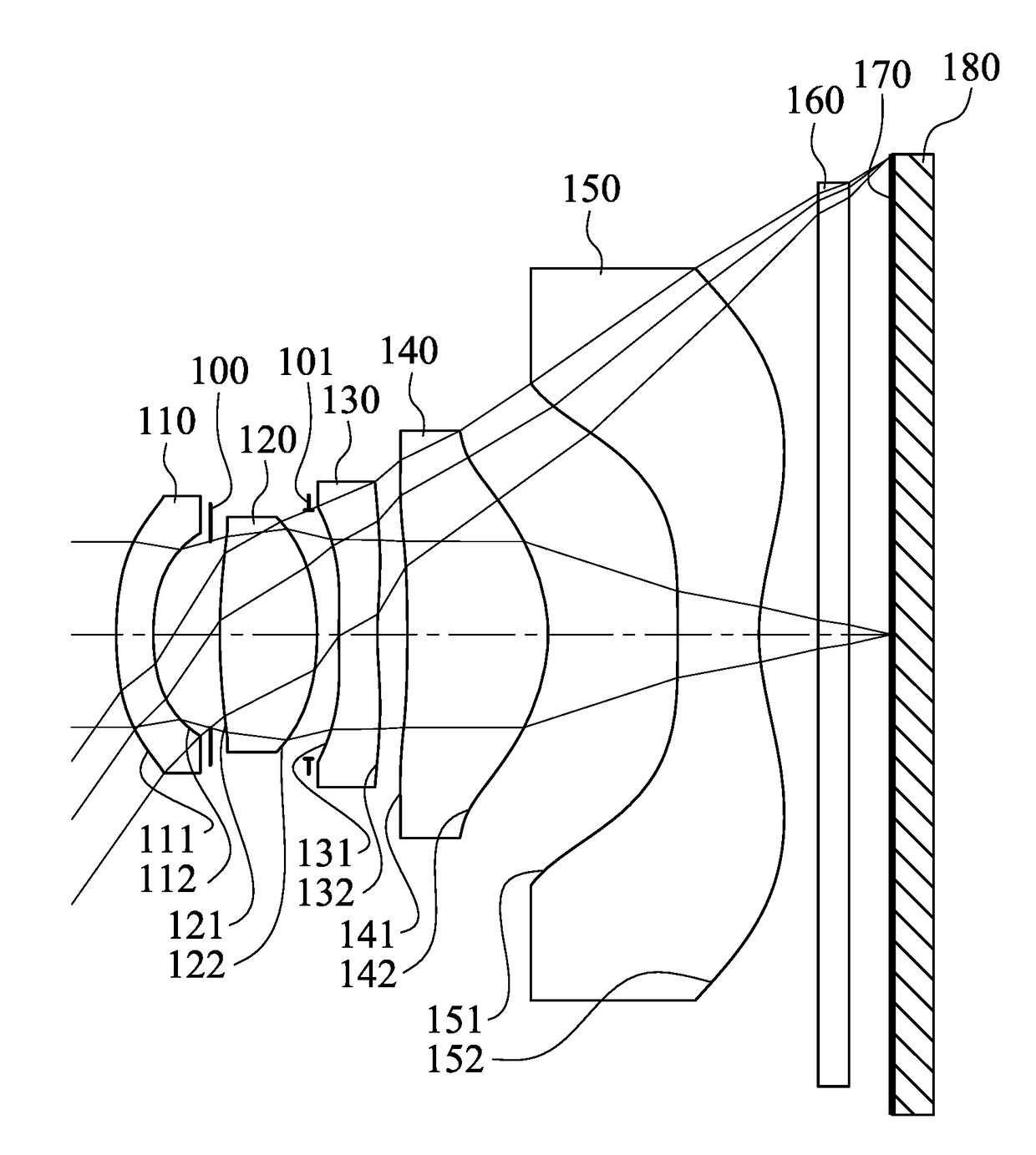
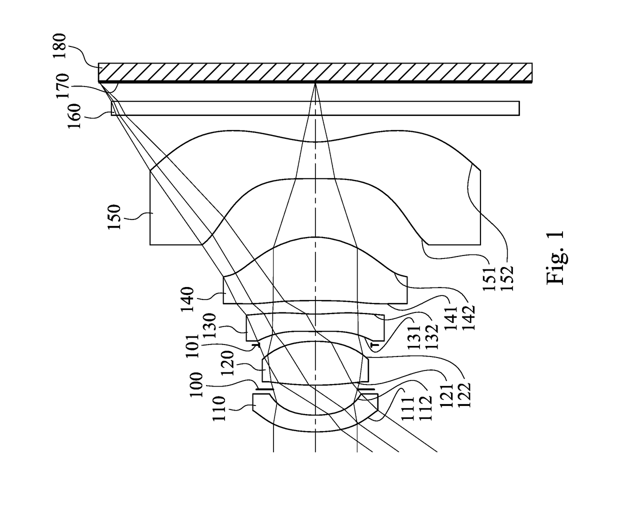
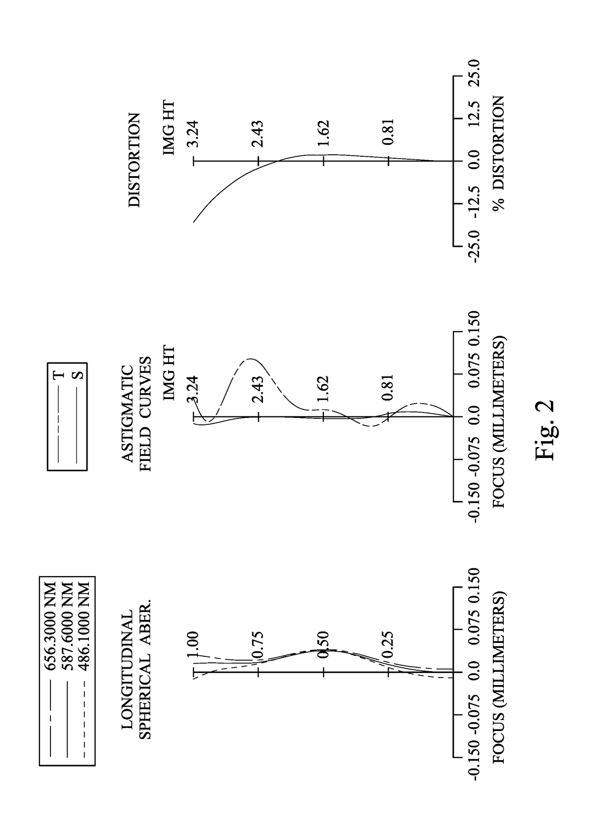
[0058]FIG. 1 is a schematic view of an imaging apparatus according to the 1st embodiment of the present disclosure. FIG. 2 shows spherical aberration curves, astigmatic field curves and a distortion curve of the imaging apparatus according to the 1st embodiment. In FIG. 1, the imaging apparatus includes an image capturing lens assembly (its reference numeral is omitted) and an image sensor 180. The image capturing lens assembly includes, in order from an object side to an image side, a first lens element 110, an aperture stop 100, a second lens element 120, a stop 101, a third lens element 130, a fourth lens element 140, a fifth lens element 150, an IR-cut filter 160 and an image surface 170, wherein the image sensor 180 is disposed on the image surface 170 of the imaging lens assembly. The imaging lens assembly includes five lens elements (110, 120, 130, 140 and 150) without additional one or more lens elements inserted between the first lens element 110 and the fifth lens element ...

2nd embodiment

[0080]FIG. 3 is a schematic view of an imaging apparatus according to the 2nd embodiment of the present disclosure. FIG. 4 shows spherical aberration curves, astigmatic field curves and a distortion curve of the imaging apparatus according to the 2nd embodiment. In FIG. 3, the imaging apparatus includes an image capturing lens assembly (its reference numeral is omitted) and an image sensor 280. The image capturing lens assembly includes, in order from an object side to an image side, a first lens element 210, an aperture stop 200, a second lens element 220, a stop 201, a third lens element 230, a fourth lens element 240, a fifth lens element 250, an IR-cut filter 260 and an image surface 270, wherein the image sensor 280 is disposed on the image surface 270 of the imaging lens assembly. The imaging lens assembly includes five lens elements (210, 220, 230, 240 and 250) without additional one or more lens elements inserted between the first lens element 210 and the fifth lens element ...

4th embodiment

[0100]FIG. 7 is a schematic view of an imaging apparatus according to the 4th embodiment of the present disclosure. FIG. 8 shows spherical aberration curves, astigmatic field curves and a distortion curve of the imaging apparatus according to the 4th embodiment. In FIG. 7, the imaging apparatus includes an image capturing lens assembly (its reference numeral is omitted) and an image sensor 480. The image capturing lens assembly includes, in order from an object side to an image side, a first lens element 410, an aperture stop 400, a second lens element 420, a stop 401, a third lens element 430, a fourth lens element 440, a fifth lens element 450, an IR-cut filter 460 and an image surface 470, wherein the image sensor 480 is disposed on the image surface 470 of the imaging lens assembly. The imaging lens assembly includes five lens elements (410, 420, 430, 440 and 450) without additional one or more lens elements inserted between the first lens element 410 and the fifth lens element ...


PUM


Abstract

An image capturing lens assembly includes five lens elements, which are, in order from an object side to an image side, a first lens element, a second lens element, a third lens element, a fourth lens element and a fifth lens element. The first lens element with negative refractive power has an image-side surface being concave in a paraxial region thereof. The second lens element has positive refractive power. The third lens element has negative refractive power. The fourth lens element has positive refractive power. The fifth lens element with negative refractive power has an image-side surface being concave in a paraxial region thereof and includes at least one convex critical point in an off-axis region thereof.

Description

RELATED APPLICATIONS[0001]This application claims priority to Taiwan Application Serial Number 106112227, filed Apr. 12, 2017, which is herein incorporated by reference.BACKGROUNDTechnical Field[0002]The present disclosure relates to an image capturing lens assembly and an imaging apparatus. More particularly, the present disclosure relates to an image capturing lens assembly and an imaging apparatus with wide field of view applicable to electronic devices.Description of Related Art[0003]With the wider application of photographing modules, installing photographing modules in various smart electronic devices, portables, mobile devices, recognition devices, entertainment systems, sporting devices and smart home assisting systems is becoming a major trend in developments for the future technology, especially portables which are in high public demands. In order to obtain more extensive experiences in utilizations, smart devices with one, two or more than three lens assemblies are becomi...

Claims


Application Information

Patent Timeline
IPC IPC(8): G02B13/00G02B9/60
CPCG02B13/0045G02B9/60G02B13/06G02B13/18
Inventor HSUEH, CHUN-CHEWU, CHIEN-HSUNCHEN, WEI-YU
Owner LARGAN PRECISION
Why Eureka
Try Eureka