
Pressure differential actuated prosthetic medical device

a technology of pressure-sensitive prosthetics and medical devices, applied in the field of medical prosthesis, can solve the problems of prone to fracture of the struts of these valves, not fully correcting the valve problem, and placing in the descending aorta instead of the heart itsel

Active Publication Date: 2018-11-08
VDYNE INC
View PDF1 Cites 23 Cited by
  • Summary
  • Abstract
  • Description
  • Claims
  • Application Information

AI Technical Summary

Benefits of technology

The patent describes a prosthetic medical device with a top stent that has a threaded structure on its outer surface. This allows for a simple way to screw the device into the patient's body to help seal and size it properly. This feature improves the efficiency and accuracy of the implantation process.

Problems solved by technology

However, one downside of this design was that it could only be placed in the descending aorta instead of the heart itself.
For this reason it did not fully correct the valve problem, only alleviate the symptoms.
However, the struts of these valves tended to fracture from fatigue over time.
However, a downside of this design is that it allows some regurgitation.
Additionally, stent-style replacement valves often continue to have the regurgitation or leakage problems of prior generations of valves, as well as require expensive materials engineering in order to cope with the 100's of millions of cycles encountered during just a few years of normal heart function.

Method used


Image

  • Pressure differential actuated prosthetic medical device
  • Pressure differential actuated prosthetic medical device
  • Pressure differential actuated prosthetic medical device

Examples


Embodiment Construction

[0086]The embodiments herein and the various features and advantageous details thereof are explained more fully with reference to the non-limiting embodiments that are illustrated in the accompanying drawings and detailed in the following description. Descriptions of well-known components and processing techniques are omitted so as to not unnecessarily obscure the embodiments herein. The examples used herein are intended merely to facilitate an understanding of ways in which the embodiments herein may be practiced and to further enable those of skill in the art to practice the embodiments herein. Accordingly, the examples should not be construed as limiting the scope of the embodiments herein.

[0087]Rather, these embodiments are provided so that this disclosure will be thorough and complete, and will fully convey the scope of the invention to those skilled in the art. Like numbers refer to like elements throughout. As used herein the term “and / or” includes any and all combinations of...


PUM


Abstract

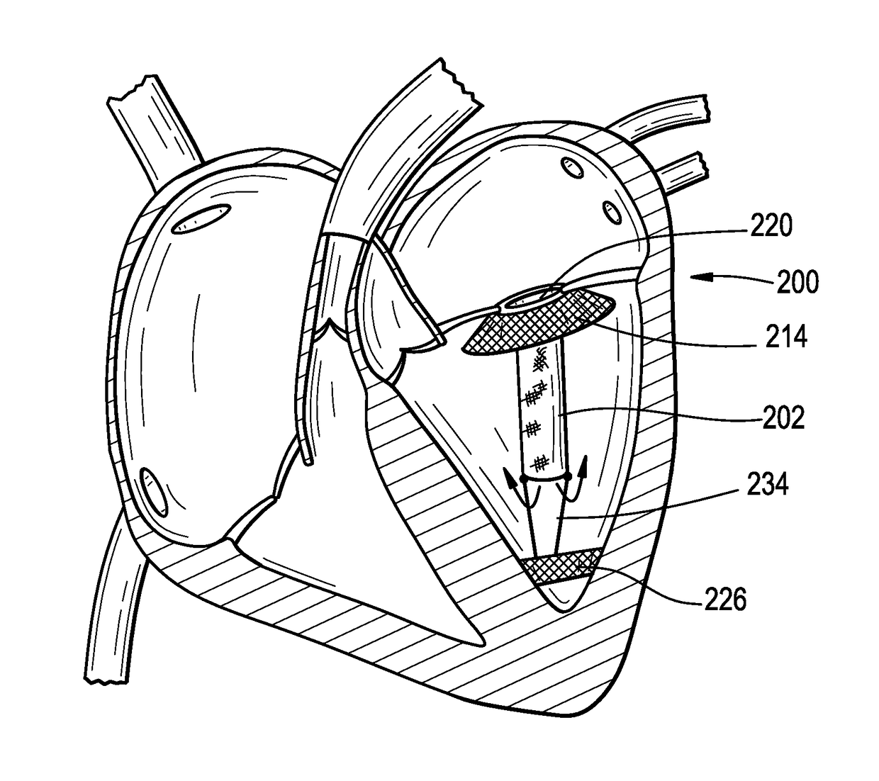
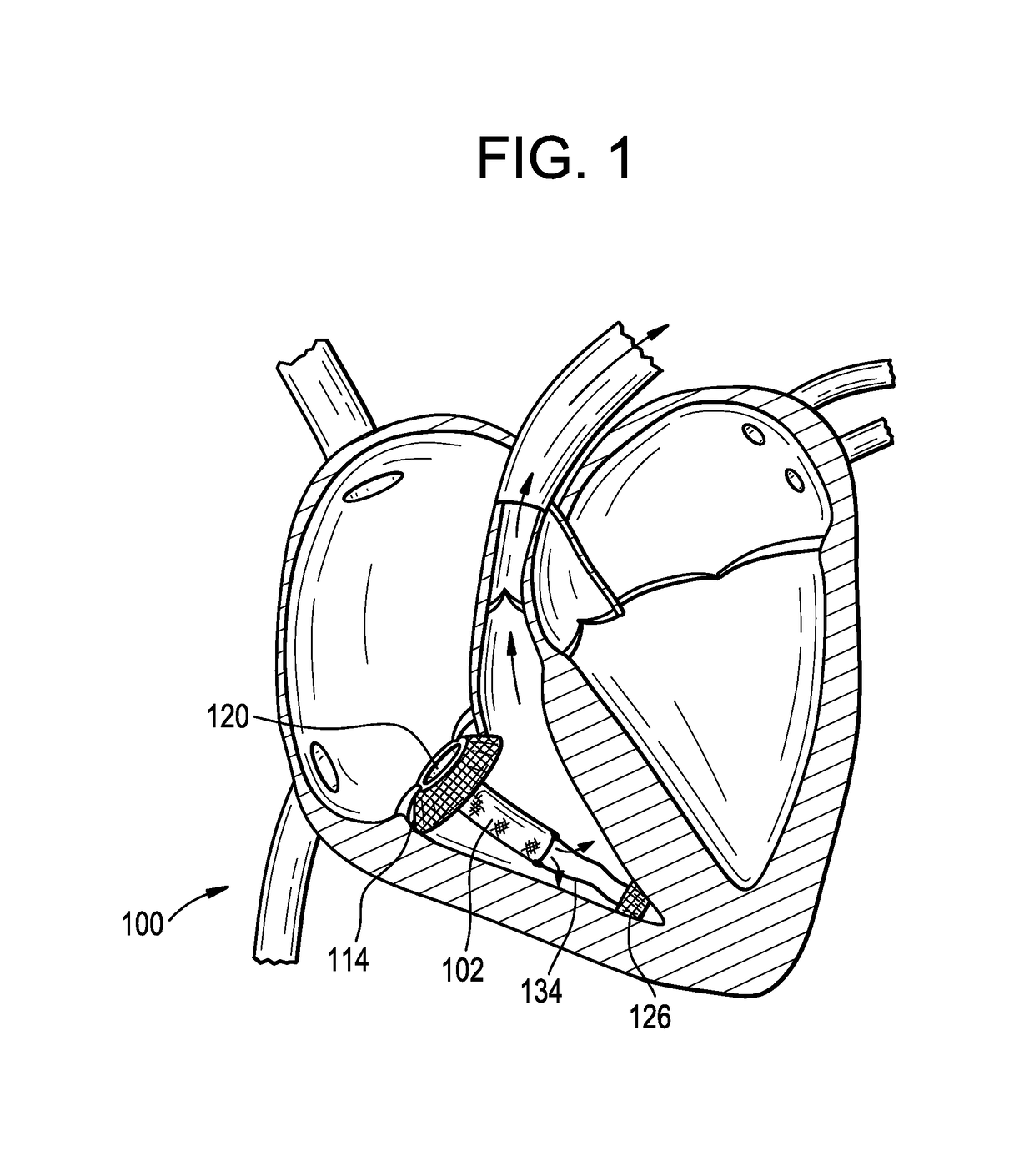
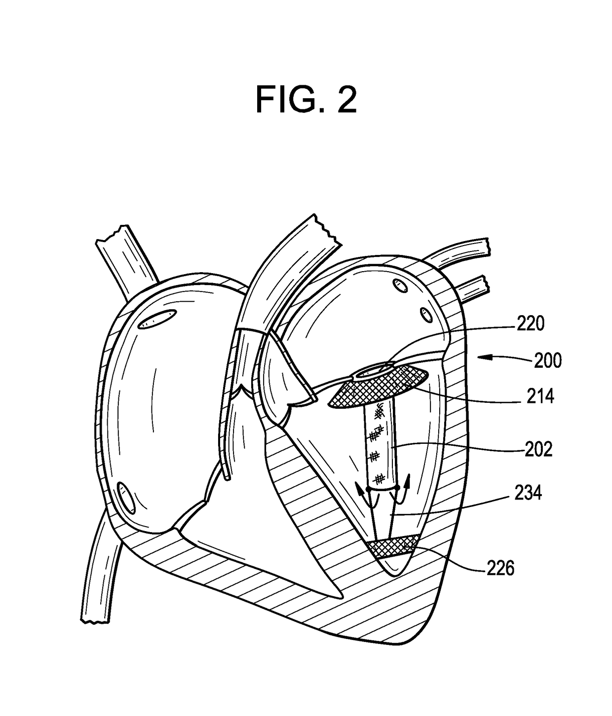
The invention relates to a medical prosthesis, and in particular a heart valve substitute comprising a pliant tubular conduit mounted on a resilient annular frame and tethered to a non-perforating anchor within the right or left ventricle of the heart, wherein the pliant tubular conduit is a reciprocating mechanical member that is compressed by pressurized working fluid within the ventricle during systole.

Description

CROSS-REFERENCE TO RELATED APPLICATIONS[0001]Provided per USPTO rules by Application Data Sheet.STATEMENT REGARDING FEDERALLY SPONSORED R&D[0002]Provided per USPTO rules by Application Data Sheet.NAMES OF PARTIES TO JOINT RESEARCH AGREEMENT[0003]Provided per USPTO rules by Application Data Sheet.REFERENCE TO SEQUENCE LISTING[0004]Provided per USPTO rules by Application Data Sheet.STATEMENT RE PRIOR DISCLOSURES[0005]Provided per USPTO rules by Application Data Sheet.BACKGROUND OF THE INVENTIONField of the Invention[0006]The invention relates to a medical prosthesis (Class 623), and in particular a heart valve substitute comprising a pliant tubular conduit (sub. 23.64) mounted on a resilient (sub. 2.14) annular frame (sub. 2.38) and tethered to a non-perforating anchor within the right or left ventricle of the heart, wherein the pliant tubular conduit is a reciprocating mechanical member (sub. 3.17) that is compressed by pressurized working fluid (sub. 3.20) within the ventricle durin...

Claims


Application Information

Patent Timeline
IPC IPC(8): A61F2/24
CPCA61F2/2418A61F2/2409A61F2/2487A61F2/2469A61F2/2421A61F2230/0069A61F2220/0008A61F2210/0061A61F2230/0065A61F2210/0014A61F2/2427A61F2230/0078A61F2/2457A61F2250/006A61F2250/0069A61F2/2412
Inventor LOZONSCHI, LUCIANLUTTER, GEORG
Owner VDYNE INC
Learn More