Miniature, pulsatile implantable ventricular assist devices and methods of controlling ventricular assist devices

a ventricular assist device and a small size technology, applied in the field of implantable ventricular assist devices, can solve the problems of increasing system complexity, affecting the function of the ventricular assist device, and the disadvantage of skin penetration and associated infection risk, and achieve the effects of reducing the risk of infection, and improving the quality of li

Active Publication Date: 2005-11-29
WORLD HEART
View PDF10 Cites 70 Cited by
  • Summary
  • Abstract
  • Description
  • Claims
  • Application Information

AI Technical Summary

Benefits of technology

[0023]The present invention provides a pumping system for assisting one or both ventricles of the heart. The pumping system of the invention has a relatively small size and is free of many disadvantages inherent in conventional blood pumps. In addition, the...

Problems solved by technology

Even the most basic drive mechanisms of the prior art are relatively complex and expensive, and typically incorporate some type of mechanical cam, linkage, or bearing arrangement subject to wear.
Some devices utilize a percutaneous tube vented to the atmosphere, which is a simple approach but has the disadvantage of a skin penetration and associated infection risk.
While eliminating the infection risk of the percutaneous vent, the volume compensator poses certain challenges: increased system complexity, an additional implanted component and potential site of infection, maintaining long-term compliance of the implanted volume compensator sac, problems associated with gas diffusion in or out of the enclosed volume, and problems associated with changes in ambient pressure, such as experienced during a plane flight.
While the pump of the '601 patent is capable of operating as a series-displacement pump, there are energy losses that result from not having the drive and pump matched for series operation.
Also, in general, the pump of the '601 patent includes a permanent magne...

Method used


Image

  • Miniature, pulsatile implantable ventricular assist devices and methods of controlling ventricular assist devices
  • Miniature, pulsatile implantable ventricular assist devices and methods of controlling ventricular assist devices
  • Miniature, pulsatile implantable ventricular assist devices and methods of controlling ventricular assist devices

Examples


Embodiment Construction

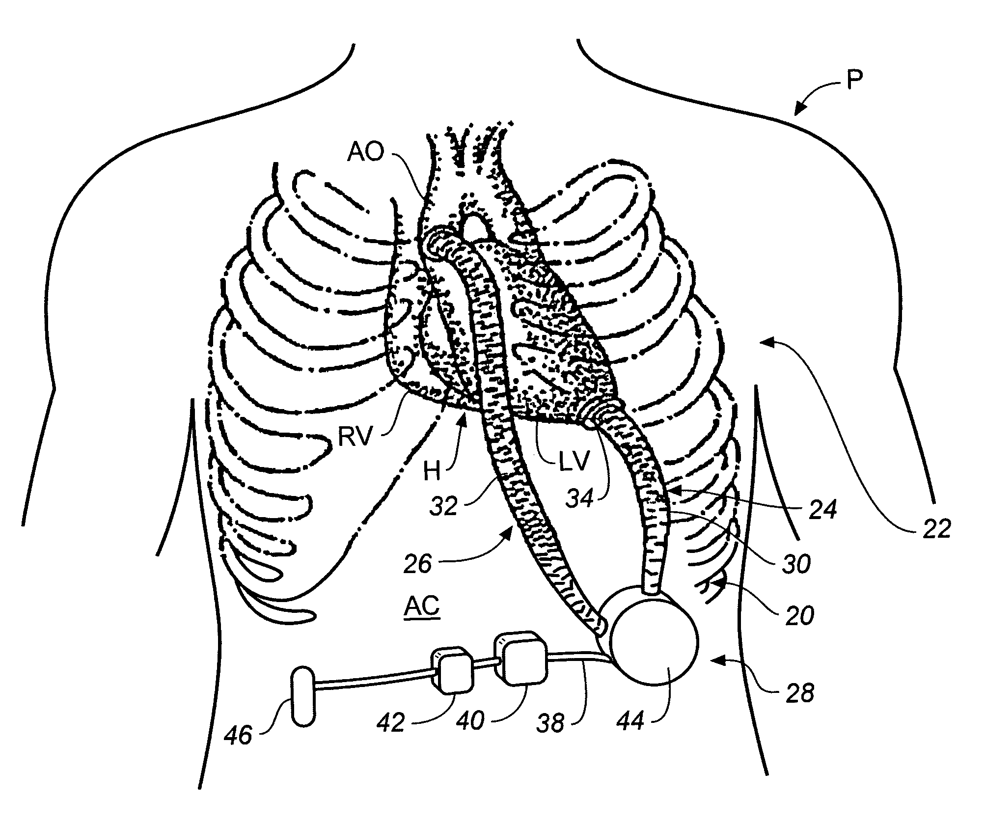
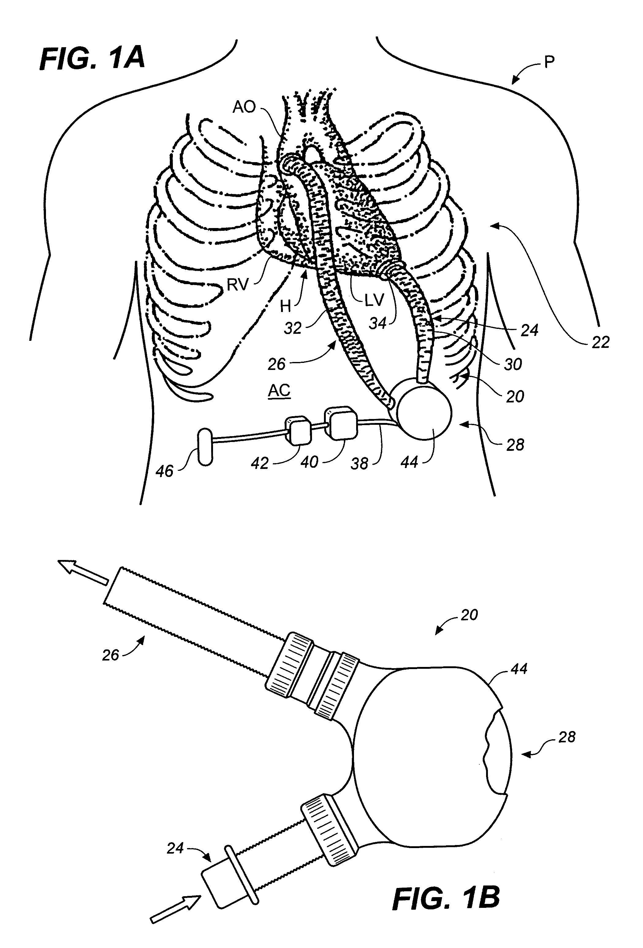
[0072]With reference first to FIG. 1A, a perspective view of a ventricular assist system 22 of the present invention is shown connected to a heart H of a patient P for the assist of a left ventricular LV. FIG. 1A shows a living human host patient P in fragmentary front elevation view, and with parts of the patient's anatomy shown in phantom or removed solely for better illustration of the salient features of the present invention. A pumping portion 20 of ventricular assist system 22 is surgically implanted into the patient's abdominal cavity AC and connected to the heart H with cannulation. The cannulation includes an inlet conduit 24 communicating blood from the patient's left ventricle LV into the pumping portion 20, and an outlet conduit 26 communicating blood from the pump 20 to the patient's aorta AO. The pumping portion 20 of ventricular assist system 22 may also be implanted in the chest cavity of the patient with similar cannulation to the LV and the patient's aorta.

[0073]Fo...


PUM


Abstract

A pumping system for assisting either or both ventricles of the heart. In one embodiment, separate devices are provided for each ventricle. In another embodiment, one device provides both right and left pumping. The pumping system is small, efficient, atraumatic, and fully implantable. In addition, the pumping system can provide pulsatile flow during systole. The ventricular assist device includes an actuator plate between a pair of serially connected pumping chambers that operate in a two-stroke mode, specifically a power stroke and a transfer stroke. The ventricular assist device also includes an electromagnetic drive system that provides adjustment to the pump pressure according to the current through an electromagnet. For the pumping system, springs provide a “spring force” on the actuator plate that is towards the high-pressure pump chamber. The bias force allows the springs to store and deliver energy from the electromagnetic drive system to provide better utilization of the pump components, and to reduce the pump size and consumption of electricity.

Description

CROSS REFERENCE TO RELATED APPLICATION[0001]This application claims the benefit of U.S. Provisional Application No. 60 / 431,288, filed Dec. 6, 2002, which is incorporated by reference herein.FIELD OF THE INVENTION[0002]The present invention relates to devices and associated methods for pumping fluids, for example, blood. More particularly, the present invention relates to implantable ventricular assist devices (VADs) that are utilized to replace the function of either the right ventricle or the left ventricle, or both, of the heart. The ventricular assist devices of the present invention include certain features that relate in the art to electric pulsatile devices.BACKGROUND OF THE INVENTION[0003]Four hundred thousand new cases of congestive heart failure are diagnosed in the United States annually, a number which will only rise in the foreseeable future with the aging of the baby-boom generation. According to the Framingham Heart Study, the five-year mortality rate for patients with...

Claims


Application Information

Patent Timeline
IPC IPC(8): A61BA61M1/10A61M1/12A61N1/362
CPCA61M1/1046A61M1/122A61M1/107A61M60/274A61M60/896A61M60/148A61M60/178A61M60/531A61M60/183A61M60/462
Inventor JASSAWALLA, JAL S.MILLER, PHILLIP J.LAFORGE, DAVID H.MUSSIVAND, TOFY
Owner WORLD HEART
Why Eureka
Try Eureka