Physical Barrier Breach Sensor

a technology of physical barrier and sensor, which is applied in the direction of electrical equipment, contact mechanisms, coupling device connections, etc., can solve the problem of immediate danger of electric shock or fir

Active Publication Date: 2018-11-15
BURKETT KARL A
View PDF4 Cites 0 Cited by
  • Summary
  • Abstract
  • Description
  • Claims
  • Application Information

AI Technical Summary

Benefits of technology

The present invention expands the use of sensors that can detect physical barrier breaches or breaks in areas where such detection is needed.

Problems solved by technology

Unfortunately, often the wires have an extended length prior to and after they are pulled apart and once the wires are pulled apart, power is not removed from the wiring at the pole's foundation or foundation side of the disconnect.
If the hot end of the wiring extending from the foundation side were to get wet, nicked, or snagged by the errant vehicle, there could be an immediate danger of electric shock or fire.

Method used


Image

  • Physical Barrier Breach Sensor
  • Physical Barrier Breach Sensor
  • Physical Barrier Breach Sensor

Examples


Embodiment Construction

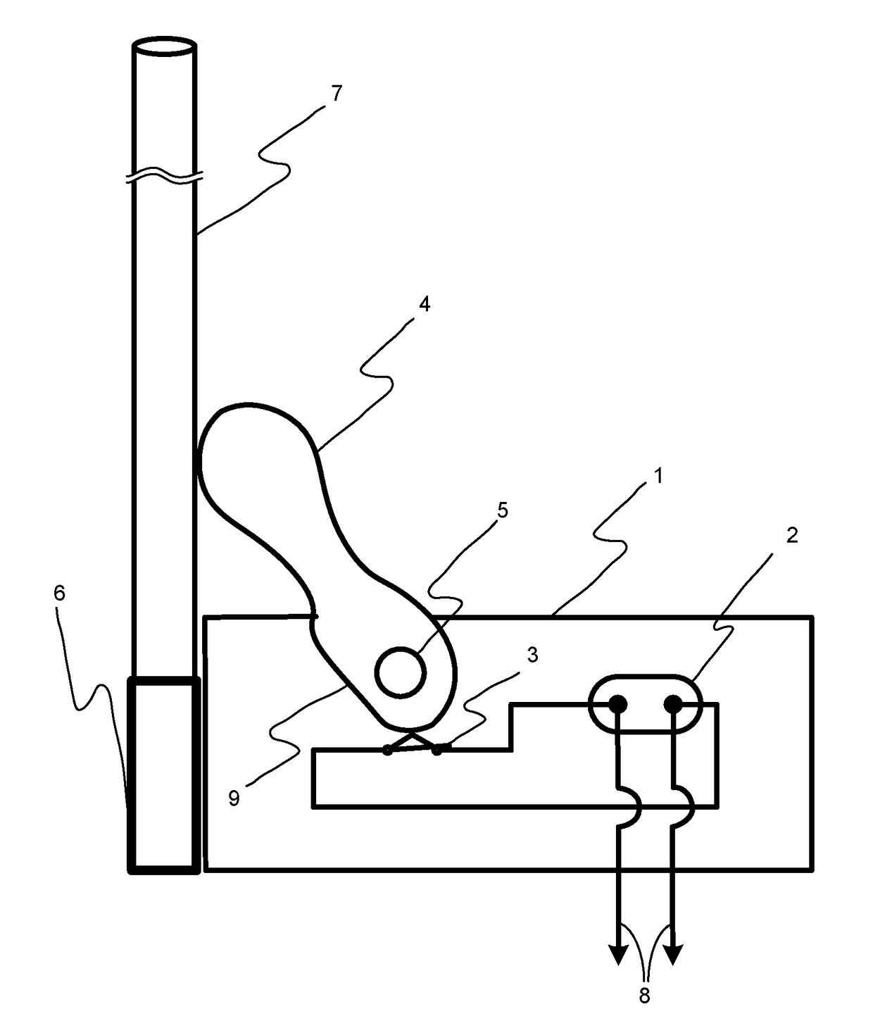
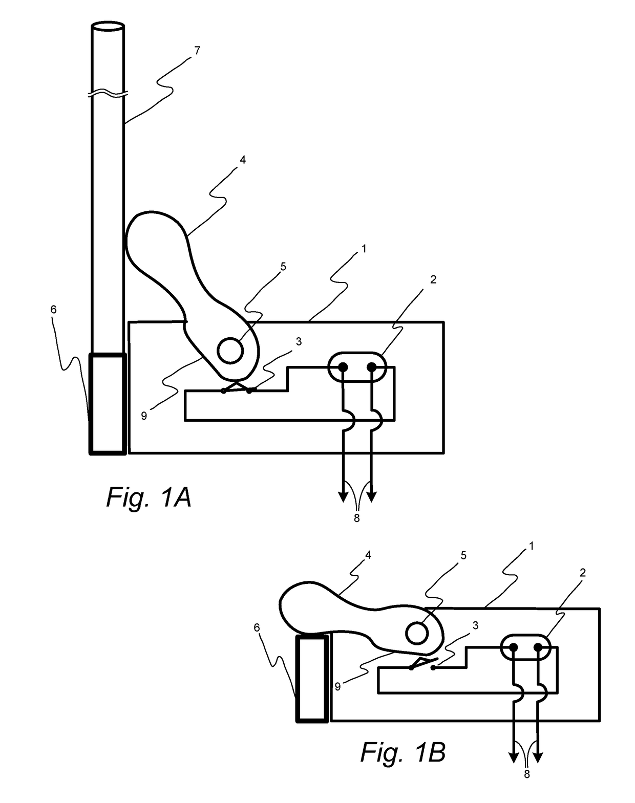
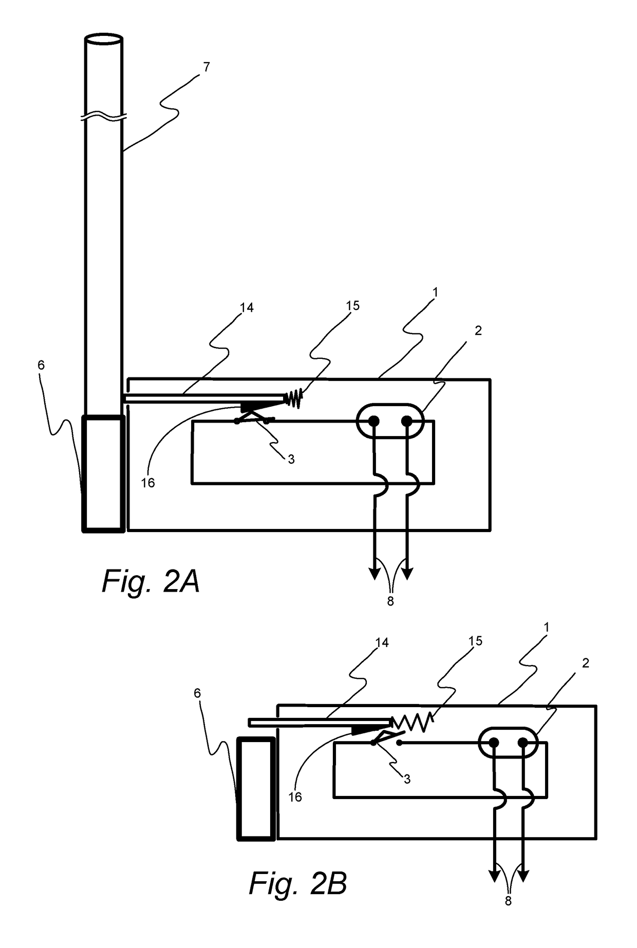
[0013]In the following detailed description, reference is made to the accompanying drawings that form a part hereof, and in which is shown by way of illustration, specific embodiments in which the invention may be practiced. These embodiments are described in sufficient detail to enable those skilled in the art to practice the invention, and it is to be understood that other embodiments may be utilized. It is also to be understood that structural, procedural and system changes may be made without departing from the spirit and scope of the present invention. The following detailed description is, therefore, not to be taken in a limiting sense, and the scope of the present invention is defined by the appended claims and their equivalents. For clarity of exposition, like features shown in the accompanying drawings are indicated with like reference numerals and similar features as shown in alternate embodiments in the drawings are indicated with similar reference numerals.

[0014]Referrin...


PUM


Abstract

A physical barrier breach sensor is disclosed that contains a frangible material that, upon displacement, opens a microswitch that de-energizes power or stops the flow of electricity to an electrical device. Displacement of the frangible material causes activation of the sensor, such as due to a vehicle colliding with a streetlight pole containing the sensor. The device is omnidirectional, operating regardless of direction of impact from the vehicle or activation, and has the ability to disconnect power when, for example, a streetlight pole or other structure (e.g., a parking gate) falls or breaks due to a shearing impact (such as a vehicle collision) or due to tension created by wind or weight failure.

Description

BACKGROUND OF THE INVENTION1. Technical Field[0001]This invention relates to electrical devices, and more particularly, to an electrical device that may be used to determine when a physical barrier has been breached, for example, by a vehicle colliding with a structure.2. Description of Related Art[0002]Most, if not all, of the states and municipalities in the continental United States have poles such as light poles, sign post, or traffic signal poles that contain or support an electrical device. Often, the poles are equipped with a base that is intended to break away when impacted by an errant vehicle.[0003]The breakaway base reduces the severity of the accident by reducing the errant vehicle's maximum change in momentum and allows the errant vehicle to continue on its path instead of being brought to a sudden stop.[0004]Within the breakaway base there is typically a pull-apart wire disconnect wherein during a collision the wires are disconnected by a wire pull apart style disconne...

Claims


Application Information

Patent Timeline
IPC IPC(8): H01H3/02H01R13/66H01R13/713
CPCH01H3/02H01R13/6683H01R13/7137H01R13/502H01R13/5213H01R13/703H01H2003/007H01H2003/0286
Inventor BURKETT, KARL A.
Owner BURKETT KARL A
Why Eureka
Try Eureka