Geared transmission unit

a transmission unit and gear technology, applied in the direction of belt/chain/gearing, toothed gearing, belt/chain/gearing, etc., can solve the problems of difficulty in further increasing the speed ratio or reducing the ratio, and achieve the effect of easy fitting into the vehicle, widening the range of the speed ratio, and increasing the speed ratio of the geared transmission uni

Active Publication Date: 2018-11-22
TOYOTA JIDOSHA KK
View PDF0 Cites 0 Cited by
  • Summary
  • Abstract
  • Description
  • Claims
  • Application Information

AI Technical Summary

Benefits of technology

[0005]Aspects of embodiments of the present disclosure have been conceived noting the foregoing technical problems, and it is therefore an object of embodiments of the present disclosure is to provide a geared transmission unit in which flexibility in arrangements of shafts, and flexibility in design and size of members coupled to the shafts are enhanced.
[0012]In the gear transmission unit according to the embodiment of the present disclosure, when a torque is applied to each of the second transmission gears, the carrier having the external gear is rotated by the rotations of the second transmission gears. Consequently, the first pinion gear meshing with the fixed gear is rotated and revolved integrally with the second pinion gear. As a result, the first transmission gear is rotated by the rotation of the second pinion gear at a predetermined speed. In the geared transmission unit according to the embodiments of the present disclosure, the second transmission gear and the external gear meshing with the second transmission gear are arranged on the outer circumferential side of the carrier. In the geared transmission unit, therefore, outer diameters and teeth numbers of the second transmission gear and the external gear are not restricted by an inner diameter of the carrier. For this reason, a speed ratio of the geared transmission unit can be increased in comparison with the conventional transmission units. In other words, a range of the speed ratio can be widened.
[0013]In addition, in the geared transmission unit according to the embodiments of the present disclosure, and the actuators and the output member are arranged on the same side in the axial direction. According to the embodiments of the present disclosure, therefore, flexibility of arrangement of the actuators etc. may be enhanced. For this reason, the geared transmission unit may be fitted easily into a vehicle.

Problems solved by technology

For this reason, it may be difficult to further increase the speed ratio or the speed reducing ratio in the planetary gear unit taught by JP-A-2010-60095.

Method used


Image

  • Geared transmission unit
  • Geared transmission unit
  • Geared transmission unit

Examples


first embodiment

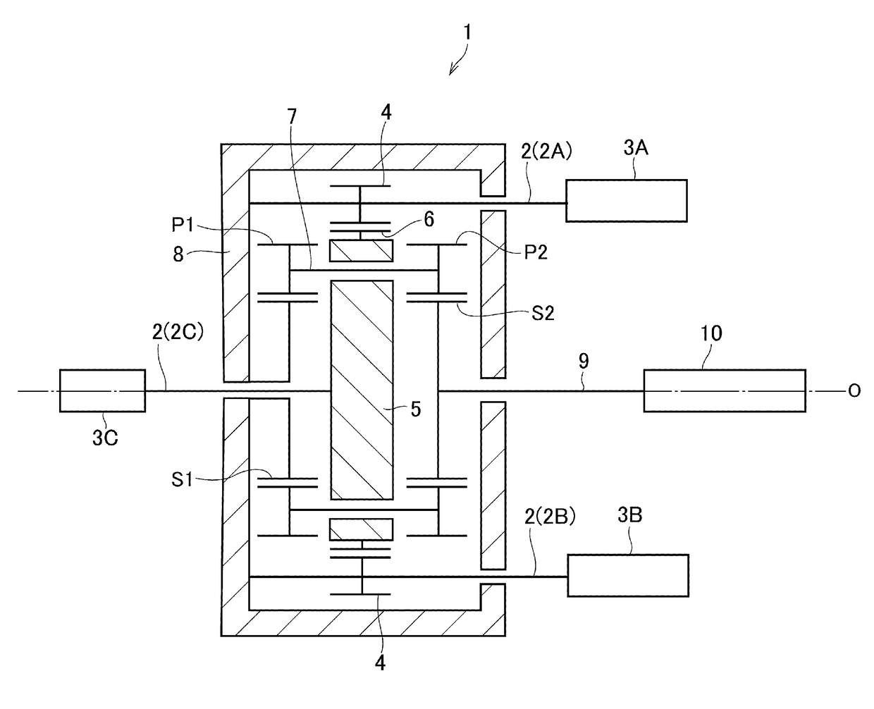
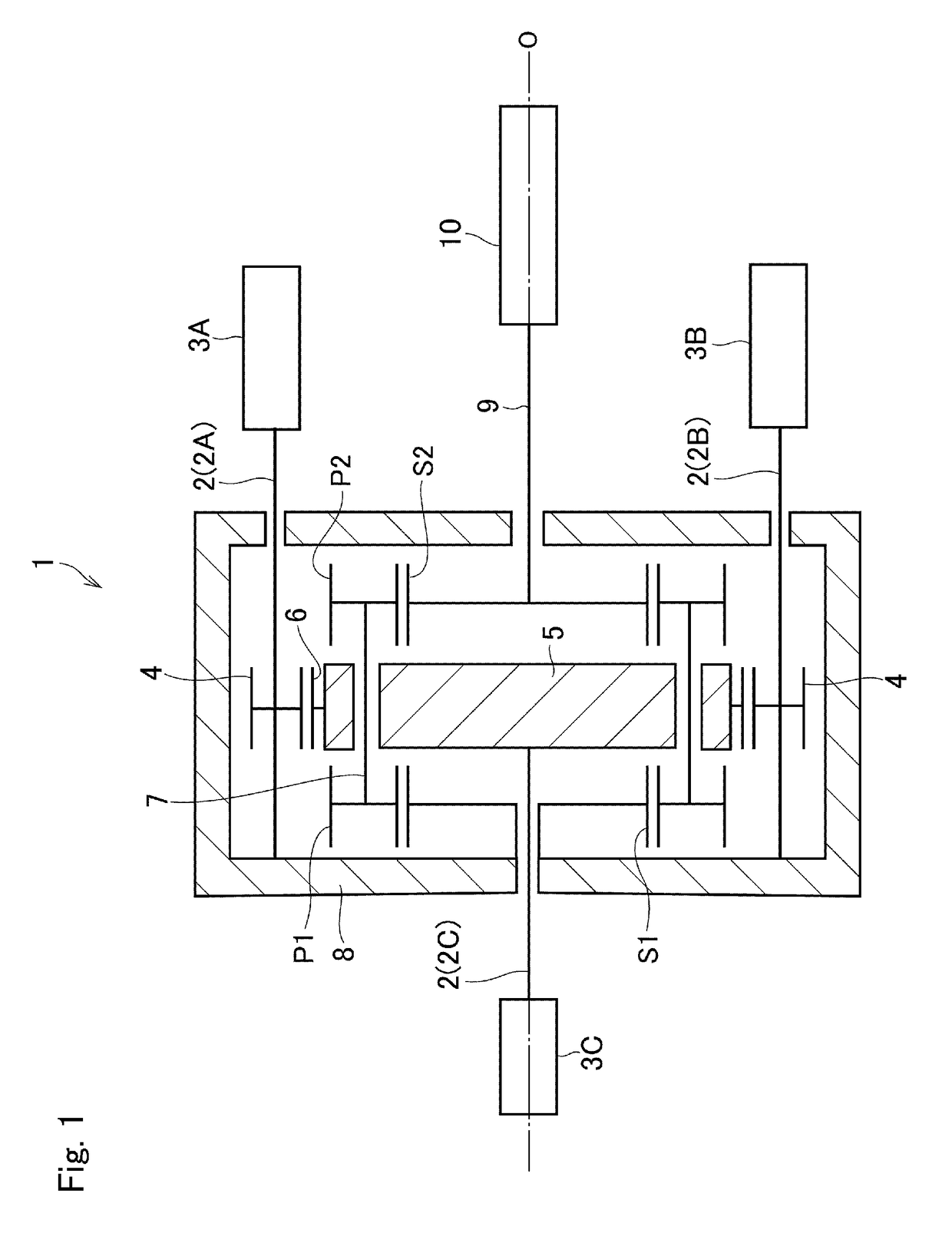
[0021]Preferred embodiments of the present disclosure will now be explained with reference to the accompanying drawings. Referring now to FIG. 1, there is shown the first embodiment of the geared transmission unit 1 according to the present disclosure. The geared transmission unit 1 shown in FIG. 1 is adapted to serve as a speed reducing device. The geared transmission unit 1 is provided with three input shafts 2 including a first input shaft 2A and a second input shaft 2B extending parallel to each other across a rotational center axis O of the geared transmission unit 1 while protruding in one direction, and a third input shaft 2C protruding in the opposite direction along the rotational center axis O. The first input shaft 2A is coupled to a first actuator 3A, the second input shaft 2B is coupled to a second actuator 3B, and the third input shaft 2C is coupled to a third actuator 3C. In the embodiments, each of the actuator 3A, 3B, and 3C individually serves as an input device. A...

second embodiment

[0028]Turning to FIG. 2, there is shown the second embodiment of the geared transmission unit 1 according to the present disclosure. According to the second embodiment, the carrier 5 comprises an annular first carrier plate 11 formed on the first sin gear S1 side, a cylindrical portion 12 extending axially from an outer circumferential portion of the first carrier plate 11, and an annular second carrier plate 13 joined to the cylindrical portion 12 on an opposite side of the first carrier plate 11. A first sun gear shaft 14 of the first sun gear S1 as the fixed gear penetrates through a first through hole 11A of the first carrier plate 11, and the output shaft 9 coupled to the second sun gear S2 as the first transmission gear penetrates through a second through hole 13A of the second carrier plate 13. Thus, the carrier 5 has a closed structure except for the first through hole 11A of the first carrier plate 11 and the second through hole 13A of the second carrier plate 13. In other ...

third embodiment

[0036]Turning to FIG. 3, there is shown the third embodiment of the geared transmission unit 1 according to the present disclosure. According to the third embodiment, the carrier 5 comprises the annular first carrier plate 11 formed on the first sun gear S1 side, the cylindrical portion 12 extending axially from the outer circumferential portion of the first carrier plate 11, and the annular second carrier plate 13 joined to the cylindrical portion 12 on an opposite side of the first carrier plate 11. The first sun gear shaft 14 of the first sun gear S1 penetrates through the first through hole 11A of the first carrier plate 11, and the output shaft 9 coupled to the second sun gear S2 penetrates through the second through hole 13A of the second carrier plate 13. The second sun gear S2 is meshed with the second pinion gear P2. Thus, the carrier 5 also has a closed structure except for the first through hole 11A of the first carrier plate 11 and the second through hole 13A of the seco...


PUM


Abstract

A geared transmission unit in which flexibility in arrangements of shafts and members coupled to the shafts is enhanced. The geared transmission unit comprises: a pair of pinion gears having different teeth numbers that rotate integrally; a carrier that rotates while supporting the pinion gears in a rotatable manner; a fixed gear meshed with a first pinion gear; a first transmission gear arranged on an inner circumferential side of the carrier while being meshed with a second pinion gear; an external gear formed on an outer circumferential face of the carrier; and second transmission gears respectively meshing with the external gear.

Description

CROSS REFERENCE TO RELATED APPLICATION[0001]The present invention claims the benefit of Japanese Patent Application No. 2017-099709 filed on May 19, 2017, with the Japanese Patent Office.BACKGROUNDField of the Disclosure[0002]Embodiments of the present disclosure relate to the art of a geared transmission unit for transmitting power through a planetary gear set.Discussion of the Related Art[0003]An example of this kind of transmission is described in JP-A-2010-60095. The planetary gear unit taught by JP-A-2010-60095 comprises two stepped pinion gears and a carrier that supports the stepped pinion gears in a rotatable manner and that is connected to a motor. The stepped pinion gears are arranged at equal intervals on the carrier, and each of the stepped pinion gears includes a fixed planetary gear and an output planetary gear. The output planetary gear is diametrically smaller than the fixed planetary gear. The planetary gear unit taught by JP-A-2010-60095 further comprises a fixed g...

Claims


Application Information

Patent Timeline
Patent Type & Authority Applications(United States)
IPC IPC(8): F16H37/06F16H37/08
CPCF16H37/065F16H37/0826F16H37/0833F16H2025/2075F16H2025/2087F16H1/28F16H57/023F16H2057/02043
Inventor ISONO, HIROSHI
Owner TOYOTA JIDOSHA KK
Why Eureka
Try Eureka