Bus bar module

a technology of bus bar and module, which is applied in the direction of propulsion by batteries/cells, cell components, batteries, etc., can solve the problems of restricted extension of lid rotation, restricted floating of electric wires from electric wire routing grooves,

Active Publication Date: 2018-11-22
YAZAKI CORP
View PDF1 Cites 5 Cited by
  • Summary
  • Abstract
  • Description
  • Claims
  • Application Information

AI Technical Summary

Benefits of technology

[0006]One or more embodiments provide a bus bar module in which floating of a lid from an electric wire routing groove can be prevented even in a case where a hinge is broken.

Problems solved by technology

In addition, in a state where the sub-engaged portion comes into contact with the protrusion wall, the further rotation of the lid is also restricted.
Therefore, the floating of the electric wire from the electric wire routing groove can also be restricted.

Method used


Image

  • Bus bar module
  • Bus bar module
  • Bus bar module

Examples


Embodiment Construction

[0022]Hereinafter, an embodiment of the present invention will be described with reference to the drawings.

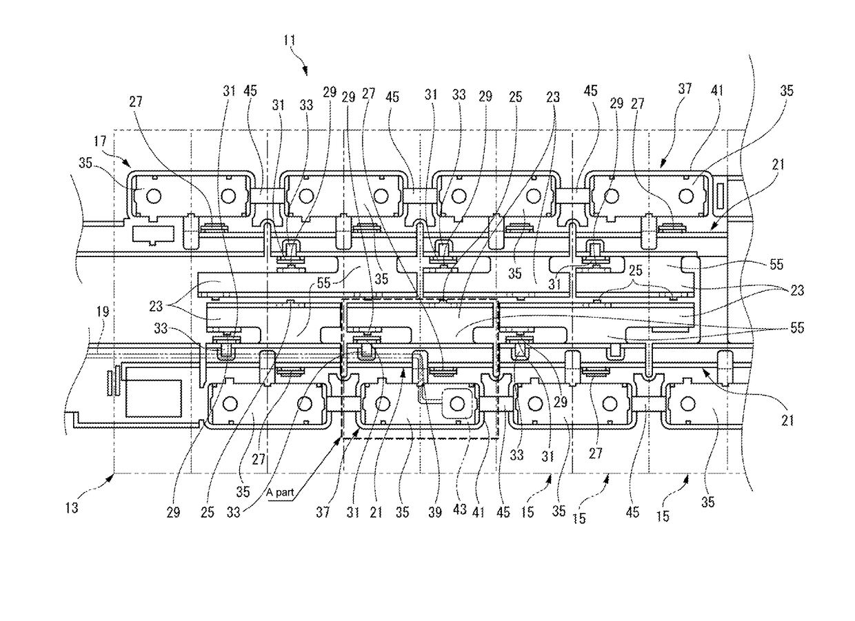
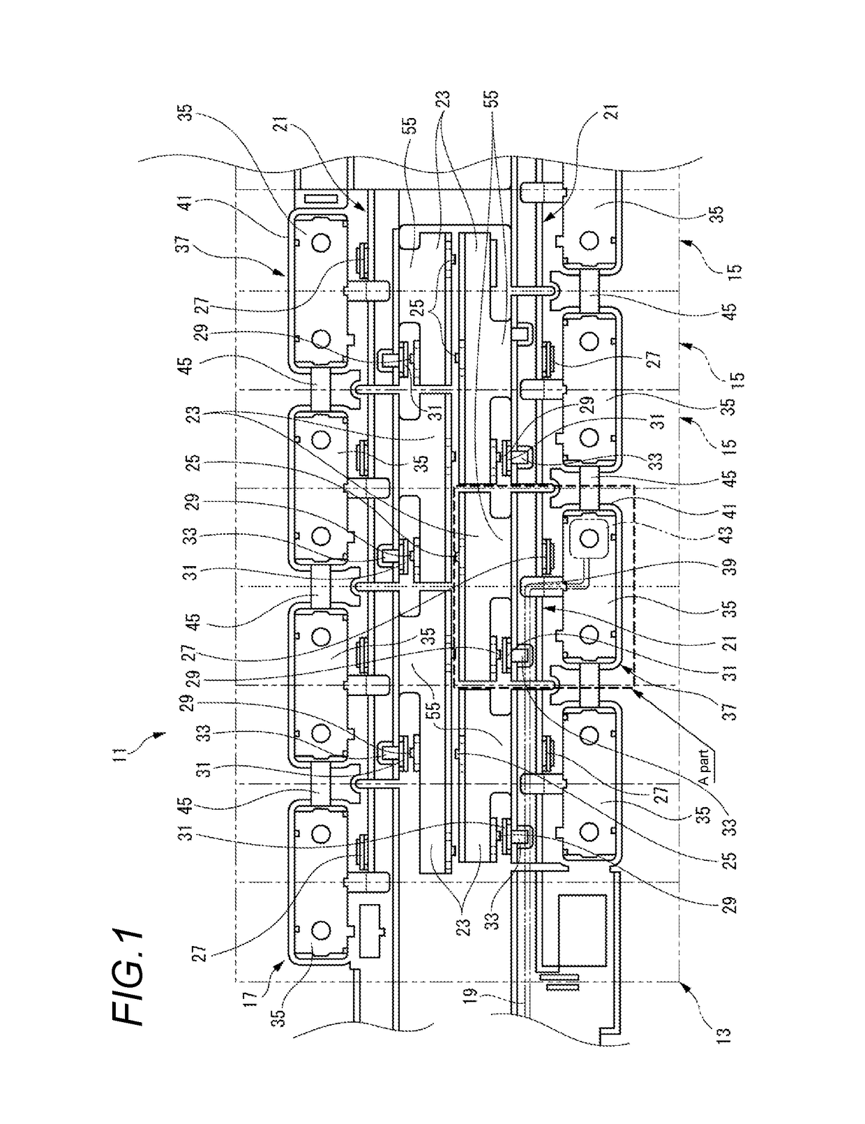
[0023]FIG. 1 is a plan view illustrating major components of a bus bar module 11 according to an embodiment of the present invention.

[0024]The bus bar module 11 according to the embodiment is attached to a battery assembly 13 of a power supply unit (not illustrated) mounted on an electric vehicle that travels using an electric motor or a hybrid vehicle that travels using an engine and an electric motor together.

[0025]The battery assembly 13 includes plural battery cells 15 that are disposed in a row and are fixed to each other. Each of the battery cells 15 includes: a rectangular battery main body; and a pair of electrodes (not illustrated) that protrude from one end and the other end of one surface of the battery main body, respectively. Among the pair of electrodes, one electrode is a positive electrode, and the other electrode is a negative electrode. In the respective batte...


PUM

PropertyMeasurementUnit
rectangular shapeaaaaaaaaaa
shapeaaaaaaaaaa
rotationaaaaaaaaaa

Abstract

A bus bar module includes an electric wire routing structure that is attached to an battery assembly including a plurality of battery cells and accommodates a plurality of bus bars in which each electrodes of the battery cells is electrically connected to each other, a plurality of electric wires connected to the battery cells via the bus bars, respectively, an electric wire routing groove formed in the electric wire routing structure and accommodating the electric wires in a pair of side walls, and a lid that is supported by a first side wall via a hinge and covers the electric wire routing groove to block a groove opening.

Description

CROSS REFERENCE TO RELATED APPLICATIONS[0001]This application claims priority from Japanese Patent Application No. 2017-099847 filed on May 19, 2017, the entire contents of which are incorporated herein by reference.BACKGROUND OF THE INVENTIONField of the Invention[0002]The present invention relates to a bus bar module.Description of Related Art[0003]A bus bar module is attached to a battery assembly mounted on a vehicle such as an electric vehicle or a hybrid vehicle. The bus bar module includes: plural bus bars that electrically connect battery cells of a battery assembly to each other; plural electric wires that are electrically connected to the respective battery cells through the bus bars; and an electric wire routing structure that accommodate the plural bus bars and routes the plural electric wires.[0004]As illustrated in FIG. 7, an electric wire routing structure 501 accommodates respective electric wires 505 in an electric wire routing groove 503 that is formed between a pa...

Claims


Application Information

Patent Timeline
Patent Type & Authority Applications(United States)
IPC IPC(8): H01M2/20H01M2/10B60L11/18B60R16/033B60R16/02H01M50/209H01M50/298H01M50/507H01M50/569
CPCH01M2/206H01M2/1077B60L11/1851B60R16/033B60R16/0215H01M2220/20H01M50/507H01M10/482H01M50/298H01M50/209H01M50/569B60L50/64Y02T10/70Y02E60/10
Inventor CHAEN, TAKAHIRO
Owner YAZAKI CORP
Why Eureka
Try Eureka