Wire plug-in aid sleeve structure for wire connection terminal

Active Publication Date: 2018-11-22
SWITCHLAB +1
View PDF0 Cites 7 Cited by
  • Summary
  • Abstract
  • Description
  • Claims
  • Application Information

AI Technical Summary

Benefits of technology

[0015]It is therefore a primary object of the present invention to provide a wire plug-in aid sleeve structure for wire connection terminal, which provides dustproof and waterproof effects and is able to enhance the security of the conductive wire assembled with the terminal. The aid sleeve is assembled in a wire plug-in hole of the terminal. The aid sleeve includes a head section, a belly section connected with the head section and a tail section connected with the belly section. The head section, the belly section and the tail section together define a guide hole for the conductive wire to plug in.

Problems solved by technology

Unless an operator uses a tool to extend into the case and push/press the metal leaf spring, the conductive wire cannot be released from the electrical connection or contact with the metal leaf spring and the conductive component.
Therefore, the conductive wire is apt to deflect or swing due to incautious touch of an operator.
This will lead to poor contact and insecurity.3. In practice, when a multi-core conductive wire is plugged into the terminal, it often takes place that the cores of the multi-core conductive wire are spread or twisted.
Therefore, the operation i

Method used


Image

  • Wire plug-in aid sleeve structure for wire connection terminal
  • Wire plug-in aid sleeve structure for wire connection terminal
  • Wire plug-in aid sleeve structure for wire connection terminal

Examples


Embodiment Construction

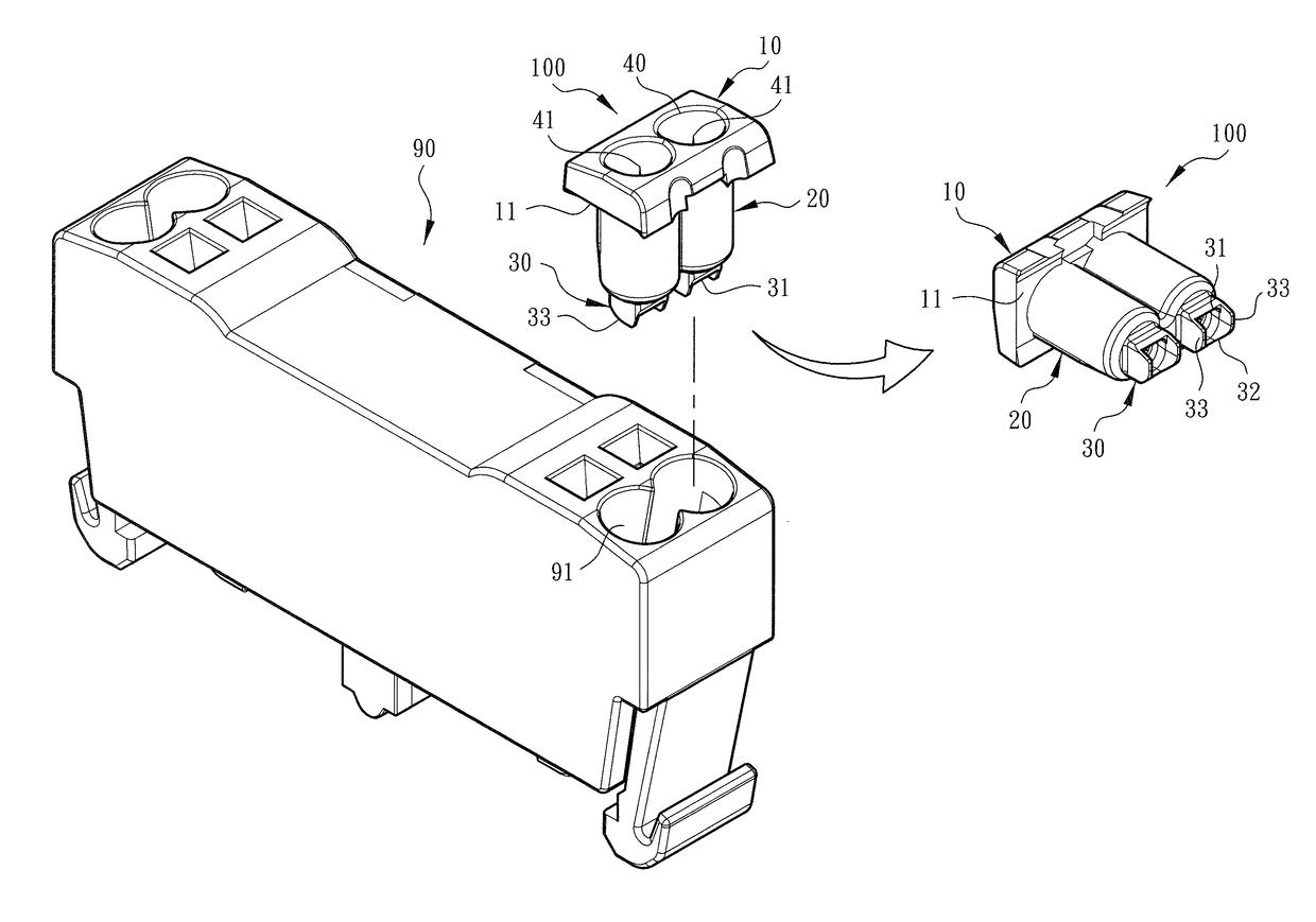
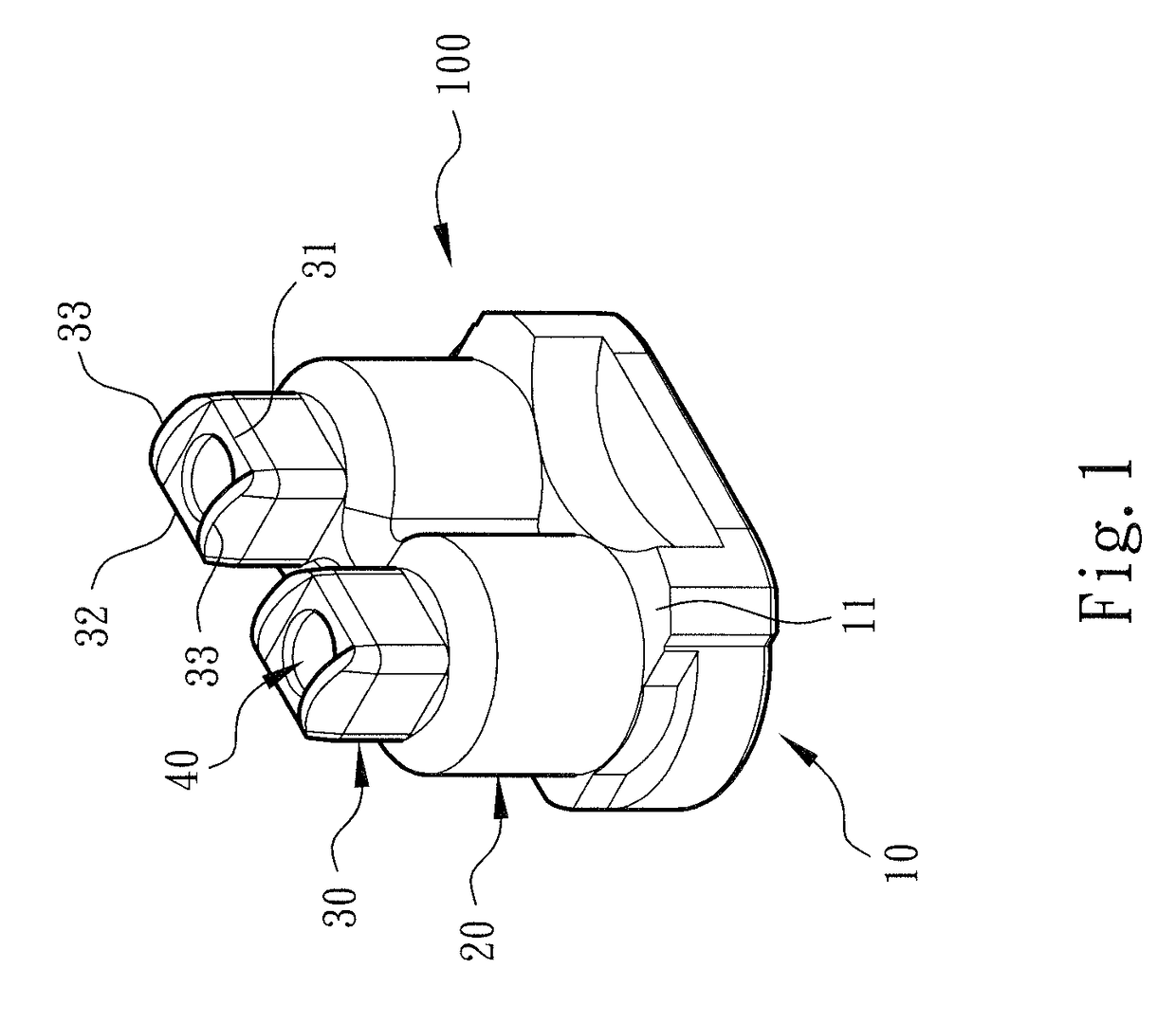
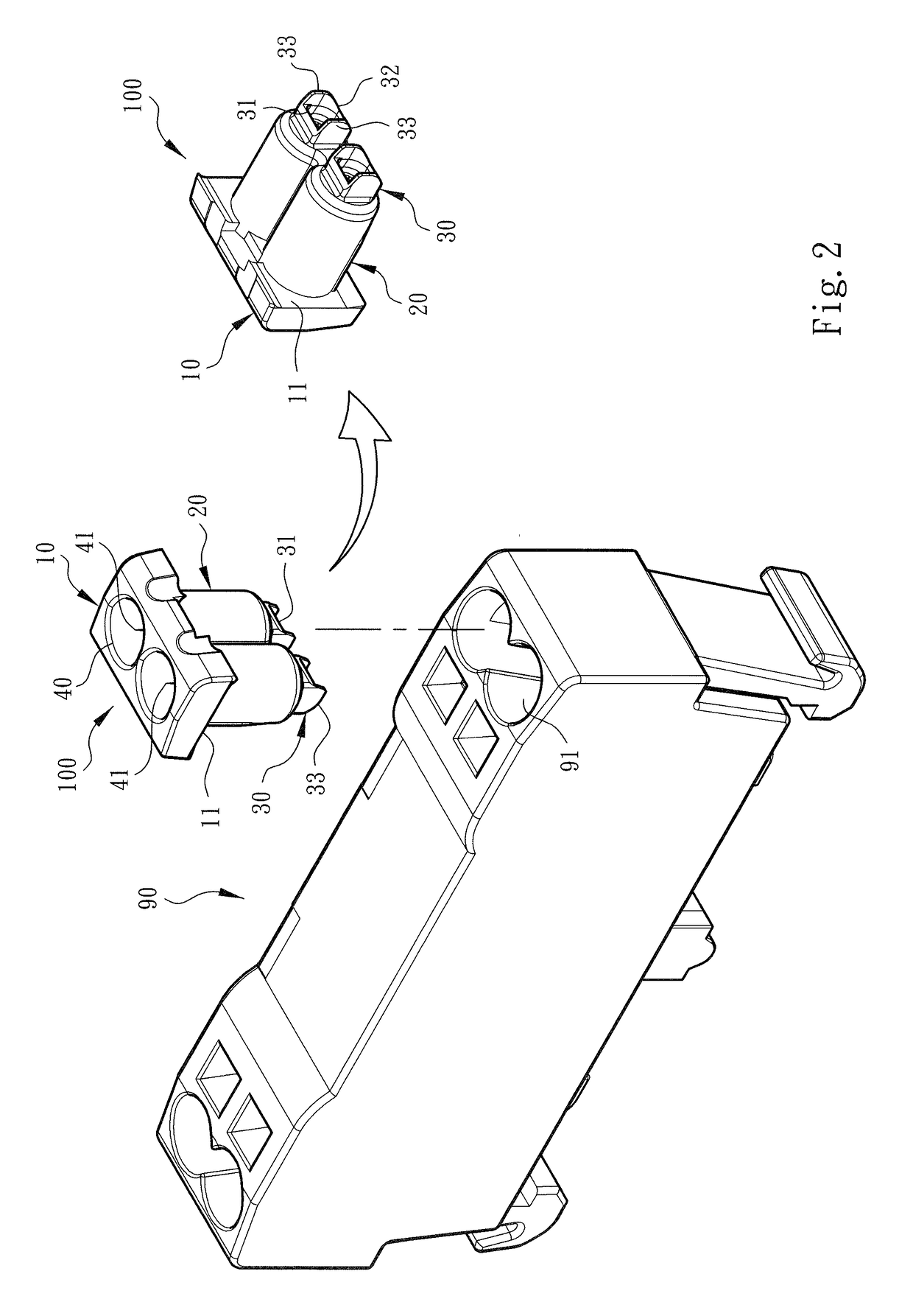
[0025]Please refer to FIGS. 1, 2 and 3. The wire plug-in aid sleeve structure for wire connection terminal of the present invention includes an aid sleeve 100 made of rubber, plastic or the like material. The aid sleeve 100 is mounted in the wire plug-in hole 91 of the terminal 90 for guiding the conductive wire 80 into the terminal 90.

[0026]As shown in the drawings, the aid sleeve 100 includes at least one head section 10, a belly section 20 connected with the head section 10 and a tail section 30 connected with the belly section 20. In this embodiment, the head section 10 of the aid sleeve 100 is connected with two cylindrical belly sections 20 and two tail sections 30 corresponding to the structural form of the terminal 90 that has two wire plug-in holes 91 on each side.

[0027]As shown in FIGS. 1, 2 and 3, the head section 10 has the form of a plate body having an area larger than the (cross-sectional) area of the belly sections 20. Accordingly, a shoulder section 11 is formed bet...


PUM


Abstract

A wire plug-in aid sleeve structure for wire connection terminal is assembled in a wire plug-in hole of the terminal. The aid sleeve includes a head section, a belly section connected with the head section and a tail section connected with the belly section. The head section, the belly section and the tail section together define a guide hole for the conductive wire to plug in. The tail section has a first side and a second side positioned on a peripheral section of the guide hole. After the conductive wire passes through the guide hole into the terminal, the metal leaf spring disposed in the terminal is facilitated to press the conductive wire toward the first side or second side.

Description

BACKGROUND OF THE INVENTION1. Field of the Invention[0001]The present invention relates generally to a wire plug-in aid sleeve structure for wire connection terminal, and more particularly to an aid sleeve mounted in a wire plug-in hole of the terminal to guide a conductive wire and help in fixing the conductive wire.2. Description of the Related Art[0002]A conventional terminal device or wire pressing terminal has an insulation case (generally made of plastic material), a metal component (or so-called electrical conductive component) and a leaf spring conductor (or so-called metal leaf spring). The metal component and the leaf spring conductor are enclosed in the insulation case to press and electrically connect with or release a conductive wire plugged in the terminal device.[0003]Such electrical terminal device can be generally classified into three types. The first type of electrical terminal device is inserted on a circuit board.[0004]The second type of electrical terminal devi...

Claims


Application Information

Patent Timeline
IPC IPC(8): H01R9/24H01R4/48
CPCH01R9/2491H01R4/4836H01R9/2416H01R9/26H01R24/20H01R4/22H01R4/48H01R13/58H01R4/48275H01R4/48365
Inventor WU, CHIH-YUANHSU, WEN BING
Owner SWITCHLAB
Why Eureka
Try Eureka