

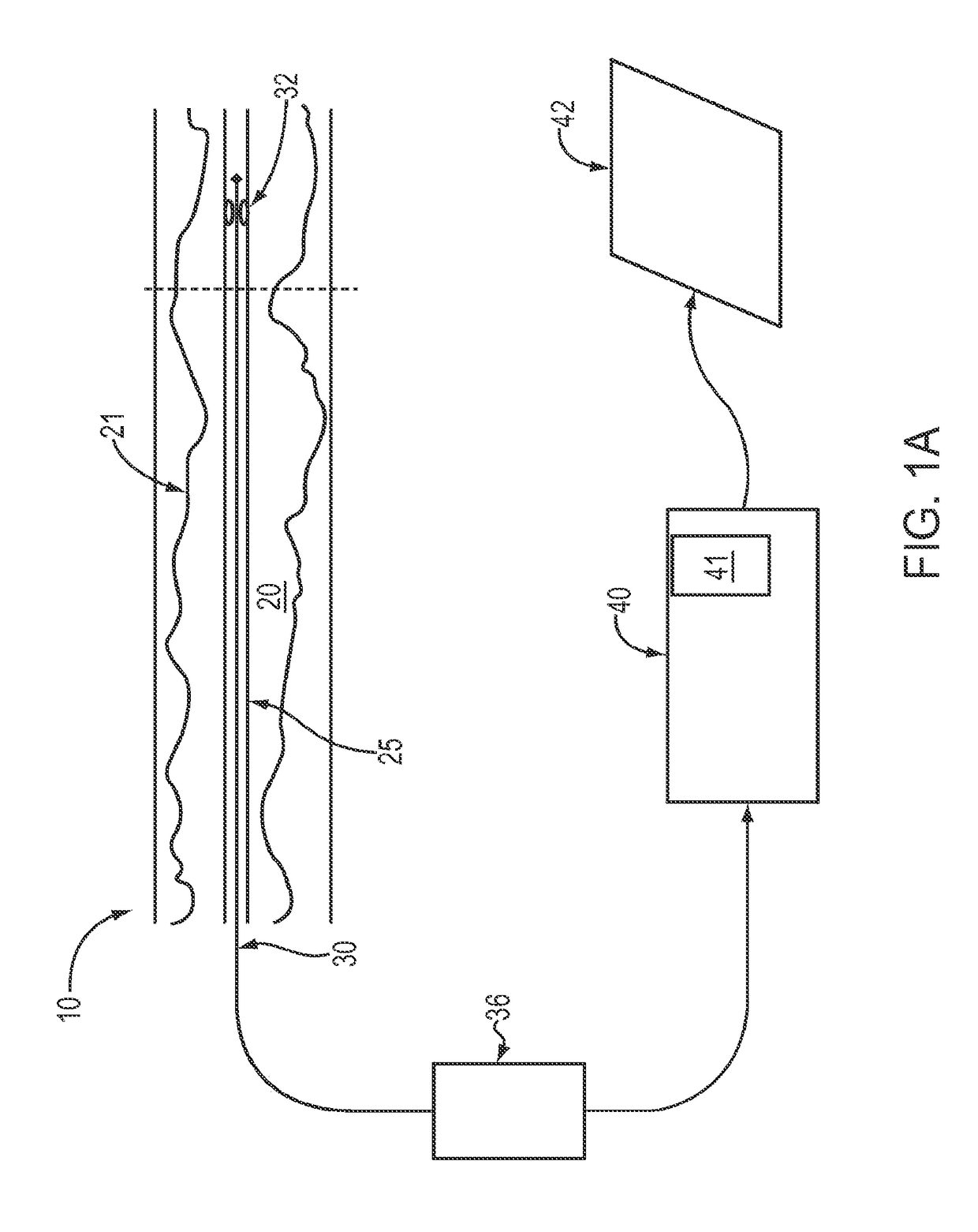
Lumen Morphology and Vascular Resistance Measurements Data Collection Systems, Apparatus and Methods
a data collection system and vascular resistance technology, applied in the field of optical coherence tomographic imaging, can solve the problems of inability to accurately determine the relationship between geometric measurements and clinically relevant variables, affecting the accuracy of the image, and requiring manual tracing of the luminal border
- Summary
- Abstract
- Description
- Claims
- Application Information
AI Technical Summary
Problems solved by technology
Method used
Image

Examples
first embodiment
[0085]a method for calculation of Rs is adapted from a model of pressure losses in stenotic lesions developed by Kirkeeide. FIG. 14 illustrates the cylindrically symmetrical geometry on which the model is based. The total resistance of the stenosis is assumed to consist of two flow-independent components and a flow-dependent components:
Rs=Rp+Rv+keQ
[0086]Here Rp represents losses due to viscous wall friction, calculated according to Poiscuille's law as:
RP=8πηC1[∑i=1NΔxiAi2-∑(Exitregions)ΔxiAi2](10)
[0087]This resistance equals the total integrated viscous losses along the vessel minus the losses in the exist regions where flow separation occurs. Exits regions are defined as the segments of the artery within which the exit angle (θ in FIG. 14) exceeds a threshold value (typically 5°). In these equations C1=0.86, based on results of experiments conducted by Kirkeeide.
[0088]The second flow-independent component of Rs in Eq. 9, which represents the additional viscous losses that occur at ...
third embodiment
[0098]The reference area, An in Eqn. 5, is calculated differently for the two models. The cylindrically symmetric model (second method) does not have any branches, therefore, An is calculated based on the average of proximal and distal areas. Thus, the velocity in the FloWorks geometry will be an average of the flows that would be encountered through the tapering section. The full 3-D model (third embodiment) includes branches, thererfore An is calculated based on the proximal area only.
[0099]The lumped resistor method show in FIG. 13 is extended for the full 3-D Computational Flow Model in FIG. 24. The resistance of the branches R1, R2 . . . RN and RDistal are each composed of the series resistors Re+Rmv. The downstream end of the every branch resistor is at Pv (10 mm Hg). The upstream end of the resistor is at the static pressure that numerical method calculates at that branch. The input pressure of the parent artery at the proximal reference is 90 mm Hg.
[0100]Rϵof each branch is ...
PUM
 Abstract
Description
Claims
Application Information