Device, method, and recording medium

a technology of recording medium and device, applied in the direction of measuring device, instrument, structural/machine measurement, etc., can solve the problems of fluid leakage and piping rupture accident, and achieve the effect of accurately predicting the deterioration tendency of the pip

Inactive Publication Date: 2018-12-06
NEC CORP
View PDF0 Cites 2 Cited by
  • Summary
  • Abstract
  • Description
  • Claims
  • Application Information

AI Technical Summary

Benefits of technology

[0016]According to the device and the method of the present invention, a deterioration tendency of a pipe can be accurately predicted.

Problems solved by technology

Many piping networks for transporting water, petroleum, gas, and the like are used beyond their useful years, and have problems of fluid leakage and piping rupture accident due to deterioration.

Method used


Image

  • Device, method, and recording medium
  • Device, method, and recording medium
  • Device, method, and recording medium

Examples


first example embodiment

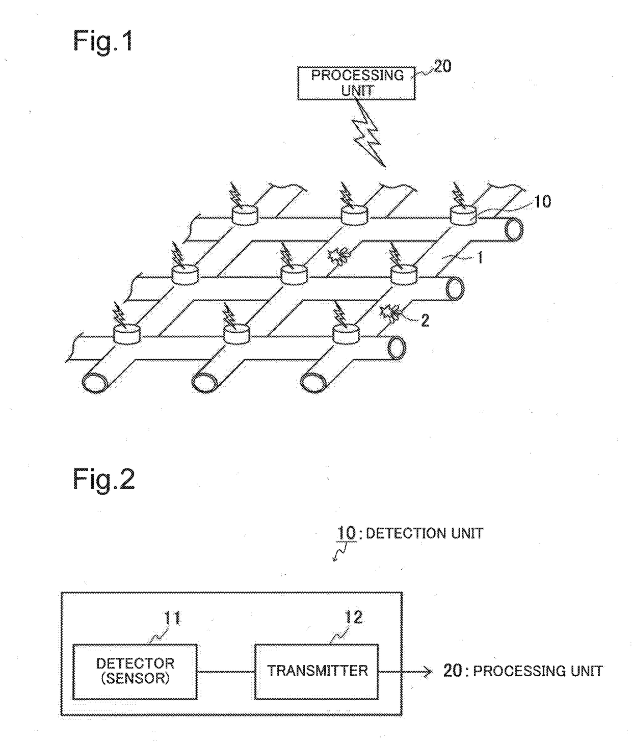
[0033]The present example embodiment is one example of a first device and a first method according to the present invention. A configuration of the device in the present example is illustrated in a schematic diagram of FIG. 1. As illustrated, the device in the present example includes a plurality of detection units 10, and a processing unit 20. Each detection unit (hereinafter referred to as “detection unit 10”) of the plurality of detection units 10 can perform wireless communication or wire communication with the processing unit 20.

[0034]The detection unit 10 is disposed in such a way as to be able to detect, via a pipe 1, an undulation (e.g., a pressure wave, vibration, or the like) propagating through the pipe 1 or fluid (e.g., liquid, gas, or the like) flowing in the pipe 1. For example, the detection unit 10 may be disposed on an outer wall surface or an inner wall surface of the pipe 1, or disposed on an outer surface of or inside an accessory (not illustrated) such as a flan...

second example embodiment

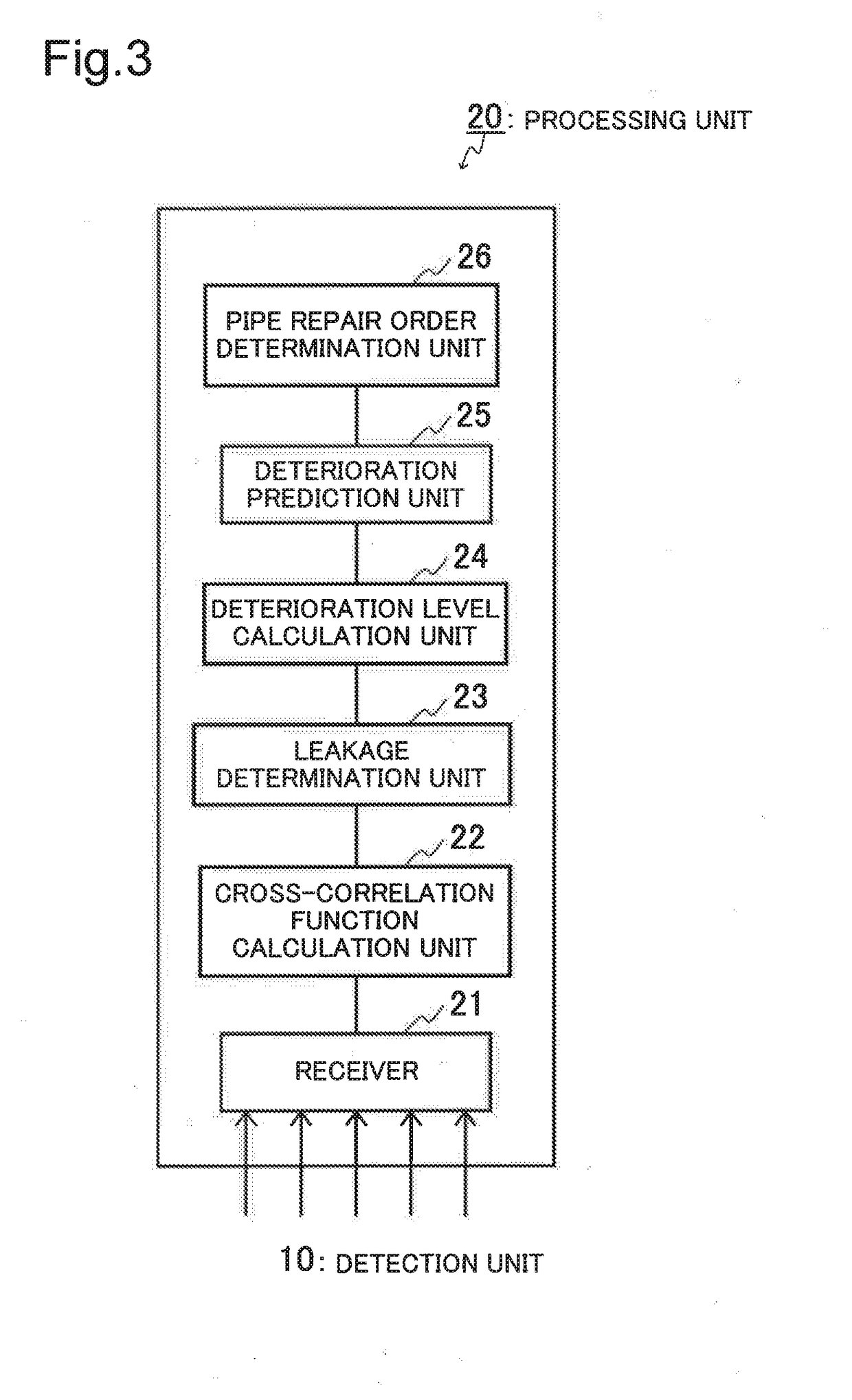
[0056]The present example embodiment is another example of the first device and the first method according to the present invention. One example of a configuration of a processing unit in a device according to the present example embodiment is illustrated in a schematic block diagram of FIG. 7. As illustrated, a processing unit 20 in the present example includes two cross-correlation function calculation unit. Apart from this, the device according to the present example embodiment is similar to the device according to the first example embodiment illustrated in FIGS. 1 to 3.

[0057]An undulation of a pipe is known to propagate in a plurality of different modes such as a torsional wave, a longitudinal wave, and a transverse wave. In the case described by way of example below in the present example embodiment, the torsional wave and the longitudinal wave that are two of the propagation modes are used.

[0058]FIG. 9 is a flowchart illustrating one example of a method according to the prese...

third example embodiment

[0066]The present example embodiment is still another example of the first device and the first method according to the present invention. A device according to the present example embodiment is the same as the device according to the first example embodiment illustrated in FIGS. 1 to 3, and a method according to the present example embodiment is the same as the method according to the first example embodiment except that a detection unit 10 detects undulations of a pipe 1 a plurality of times.

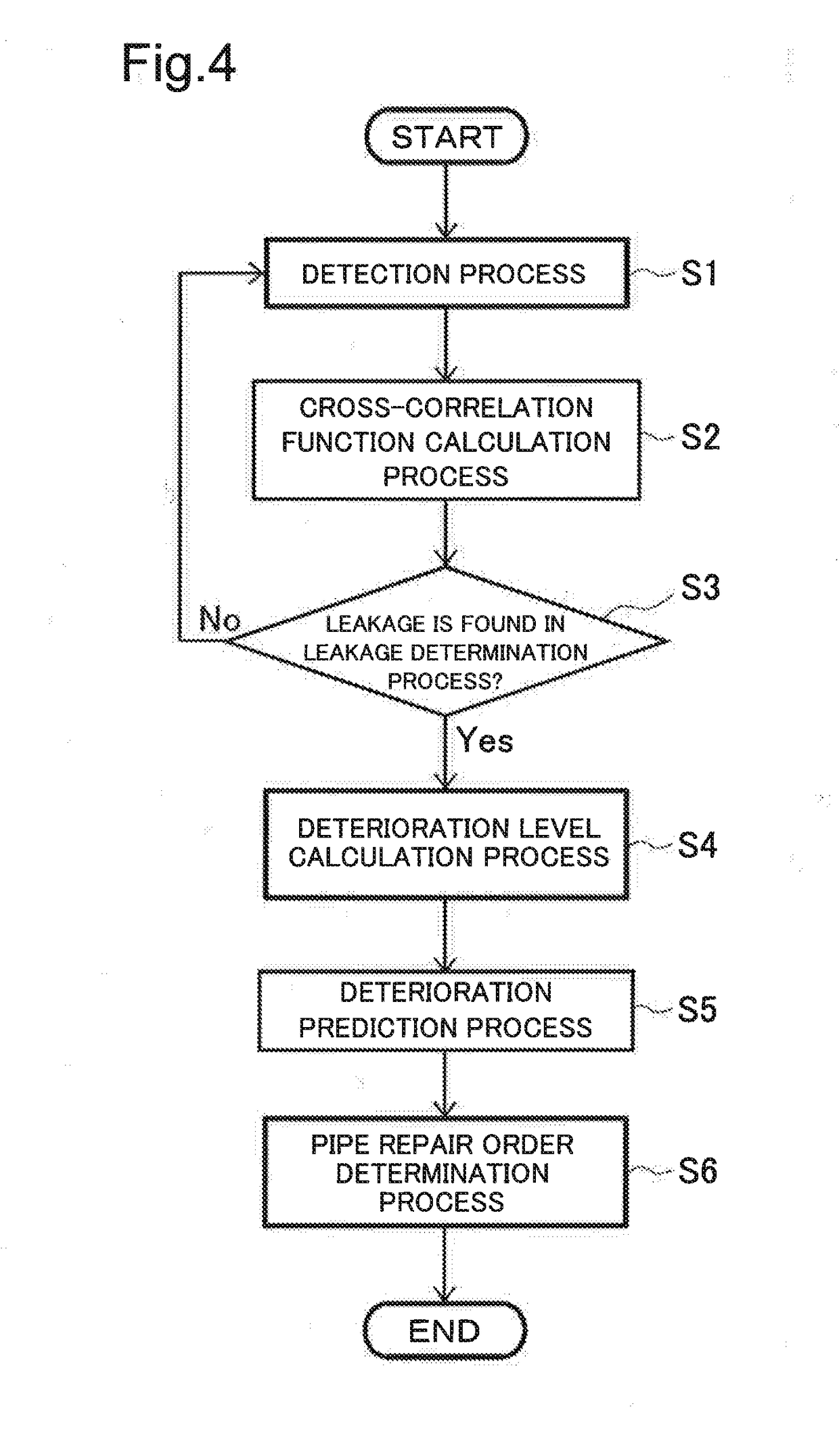
[0067]FIG. 11 is a flowchart illustrating one example of a method according to the present example embodiment. In the method according to the present example embodiment, N sets of (2N pieces) detection units 10 disposed in N pipes 1 first detect undulations a plurality of times while changing time zones of detection (step S1). The detected undulations are transmitted to a processing unit 20 by a transmitter 12 of the detection unit 10, and received by a receiver 21 of the processing unit 20.

[0...


PUM


Abstract

Provided is a device that may accurately predict a deterioration tendency of a pipe. The device includes a plurality of detection units 10, a cross-correlation function calculation unit 22, a deterioration level calculation unit 24, and a deterioration prediction unit 25. The plurality of detection units 10 detect undulations at least two locations in a pipe in which a fluid flows. The cross-correlation function calculation unit 22 calculates a cross-correlation function of the pipe, based on the undulations at the at least two locations in the pipe detected by the plurality of detection units 10. The deterioration level calculation unit 24 calculates a deterioration level of the pipe, based on a shape of the cross-correlation function of the pipe. The deterioration prediction unit 25 predicts a deterioration tendency of the pipe, based on a temporal change of the deterioration level.

Description

[0001]This application is a National Stage Entry of PCT / JP2016 / 085756 filed on Dec. 1, 2016, which claims priority from Japanese Patent Application 2015-236985 filed on Dec. 3, 2015, the contents of all of which are incorporated herein by reference, in their entirety.TECHNICAL FIELD[0002]The present invention relates to a device, a method, and a recording medium.BACKGROUND ART[0003]Many piping networks for transporting water, petroleum, gas, and the like are used beyond their useful years, and have problems of fluid leakage and piping rupture accident due to deterioration. In order to solve these problems, it is necessary to repair a pipe at an appropriate time. A pipe is generally repaired based on the number of years for which the pipe has been laid, but is ideally repaired according to a plan depending on a deterioration level of the pipe.[0004]PTL 1 describes a method of forming a repair plan of a pipe, based on a leakage amount estimated from a pressure wave generated by water ...

Claims


Application Information

Patent Timeline
Patent Type & Authority Applications(United States)
IPC IPC(8): G01M3/24
CPCG01M3/243
Inventor INOUE, HIROFUMIKUMURA, TAKAHIROTAKATA, SOICHIRO
Owner NEC CORP
Why Eureka
Try Eureka