Controller for internal combustion engine and method for controlling internal combustion engine

a technology of internal combustion engine and control device, which is applied in the direction of electric control, machines/engines, mechanical equipment, etc., can solve the problems of difficult to set the air-fuel ratio, the air-fuel ratio is different between cylinders, and the vapor of fuel is not always uniformly distributed to the cylinders, so as to increase the combustion deterioration tendency and increase the differences between cylinders

Active Publication Date: 2020-08-25
TOYOTA JIDOSHA KK
View PDF14 Cites 0 Cited by
  • Summary
  • Abstract
  • Description
  • Claims
  • Application Information

AI Technical Summary

Benefits of technology

[0008]In the above configurations, the difference limiting process limits and decreases the difference of the air-fuel ratio in the rich combustion cylinder and the air-fuel ratio in the lean combustion cylinder resulting from the dither control process on condition that the purge control process is controlling the flow rate of the fuel vapor at a value greater than zero. When the difference of the air-fuel ratio in the rich combustion cylinder and the air-fuel ratio in the lean combustion cylinder is small, the combustion deterioration tendency resulting from dither control will be more limited than when the difference of the air-fuel ratio in the rich combustion cylinder and the air-fuel ratio in the lean combustion cylinder is large. Thus, the difference limiting process decreases the combustion deterioration tendency resulting from dither control, as compared with when the dither control is not executed, that would increase the difference in the fuel vapor distributed between cylinders by purge control.
[0010]In the above configuration, the difference limiting process is performed on condition that the purge parameter is greater than or equal to the threshold value. This allows the dither control process to be performed without any limitation imposed by the difference limiting process when the amount of fuel vapor is small and the combustion deterioration tendency resulting from the execution of the dither control will not increase differences between the cylinders in the distributed fuel vapor.
[0012]Even when the purge rate is the same, the ratio of the flow rate of the fuel vapor to the intake air flow rate increases changes in accordance with the concentration of the fuel vapor in the canister. An increase in the ratio of the flow rate of the fuel vapor to the intake air flow rate will increase the combustion deterioration tendency resulting from the execution of the dither control and thereby increase differences between the cylinders in the distributed fuel vapor. In the above configuration, the difference limiting process is performed when the ratio of the flow rate of the fuel vapor to the intake air flow rate is greater than or equal to the threshold value. This minimizes situations in which the difference limiting process is actually performed.
[0016]The combustion deterioration tendency resulting from the execution of the dither control that increase differences between the cylinders in the distributed fuel vapor may differ in accordance with the operating point of the internal combustion engine. In the above configuration, the upper limit guard value is variably set in accordance with the operating point of the internal combustion engine to minimize difference limiting.

Problems solved by technology

Thus, it is difficult to set the air-fuel ratio so as to avoid unsatisfactory combustion as compared with when controlling the air-fuel ratio in every one of the cylinders.
When performing purge control, fuel vapor is not always uniformly distributed to the cylinders.
This may result in the air-fuel ratio differing between cylinders.
Thus, when performing dither control during purge control, the combustion deterioration tendency resulting from dither control will further increase the difference in the fuel vapor distributed between cylinders by purge control.
When the difference of the air-fuel ratio in the rich combustion cylinder and the air-fuel ratio in the lean combustion cylinder is small, the combustion deterioration tendency resulting from dither control will be more limited than when the difference of the air-fuel ratio in the rich combustion cylinder and the air-fuel ratio in the lean combustion cylinder is large.
Thus, the difference limiting process decreases the combustion deterioration tendency resulting from dither control, as compared with when the dither control is not executed, that would increase the difference in the fuel vapor distributed between cylinders by purge control.
An increase in the ratio of the flow rate of the fuel vapor to the intake air flow rate will increase the combustion deterioration tendency resulting from the execution of the dither control and thereby increase differences between the cylinders in the distributed fuel vapor.

Method used


Image

  • Controller for internal combustion engine and method for controlling internal combustion engine
  • Controller for internal combustion engine and method for controlling internal combustion engine
  • Controller for internal combustion engine and method for controlling internal combustion engine

Examples


first embodiment

[0024]A controller for an internal combustion engine according to a first embodiment will now be described with reference to the drawings.

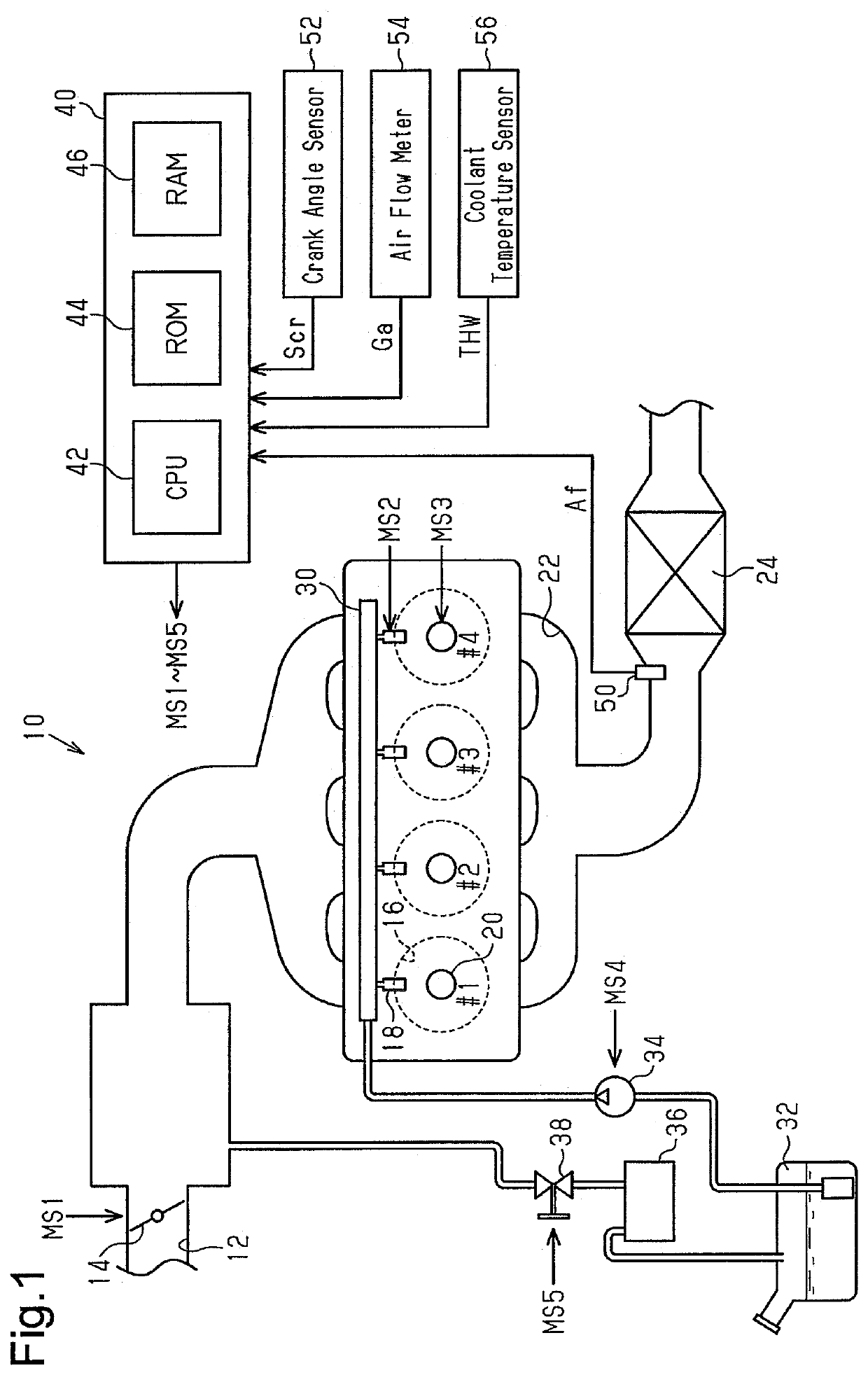
[0025]In an internal combustion engine 10 shown in FIG. 1, air drawn from an intake passage 12 flows through a throttle valve 14 into a combustion chamber 16 of each cylinder. A fuel injection valve 18, which injects fuel, and an ignition device 20, which generates spark discharges, project into the combustion chamber 16. A mixture of air and fuel is burned in each combustion chamber 16, and the burned air-fuel mixture is discharged as exhaust gas out of the combustion chamber 16 into an exhaust passage 22. A three-way catalyst 24 having an oxygen storage capability is arranged in the exhaust passage 22.

[0026]The fuel injection valve 18 injects fuel into a delivery pipe 30. A fuel pump 34 feeds the delivery pipe 30 with fuel from a fuel tank 32. Some of the fuel stored in the fuel tank 32 vaporizes into fuel vapor. The fuel vapor is collected by a...

second embodiment

[0053]A second embodiment will now be described focusing on differences from the first embodiment.

[0054]FIG. 5 shows the processing procedures of the request-value output processor M18 in the second embodiment. The process shown in FIG. 5 is achieved by the CPU 42, for example, repeatedly executing the programs stored in the ROM 44 in predetermined cycles. In FIG. 5, the processes corresponding to those of FIG. 3 are denoted by the same step numbers for the sake of convenience.

[0055]In the series of processes shown in FIG. 5, after the CPU 42 calculates the base request value α0 (S12), the CPU 42 variably sets the specified value Rpth in accordance with the purge concentration Dp and determines whether or not the target purge rate Rp* is greater than or equal to the specified value Rpth (S14a). In detail, when the purge concentration Dp is large, the CPU 42 sets the specified value Rpth to be less that that when the purge concentration Dp is small. That is, as the purge concentratio...


PUM


Abstract

A controller for an internal combustion engine includes processing circuitry that performs a dither control process on condition that a temperature increase request of a catalyst is made. The processing circuitry operates fuel injection valves so that during the dither control process, one or more cylinders are lean combustion cylinders in a first period and another one or more cylinders are rich combustion cylinders and so that the average value of an exhaust gas-fuel ratio is a target air-fuel ratio in a second period including the first period. The dither control process is restricted in a manner that, on condition that the rich process is performed, the degree of richening of the richest exhaust gas-fuel ratio of exhaust gas-fuel ratios in the cylinders is reduced.

Description

BACKGROUND ART[0001]The present invention relates to a controller for an internal combustion engine and a method for controlling an internal combustion engine.[0002]Japanese Patent Application Publication No. 2012-57492 describes an example of a controller executing perturbation control (dither control) so that in response to a warm-up request (temperature increase request) of a catalyst device (catalyst), the air-fuel ratio in some of a plurality of cylinders is set to be richer than the stoichiometric air-fuel ratio and the air-fuel ratio in the remaining cylinders is set to be leaner than the stoichiometric air-fuel ratio.[0003]Purge control that is known in the art draws fuel vapor into an intake passage from a fuel tank storing fuel.[0004]When performing dither control, a difference is produced between the air-fuel ratio in a rich combustion cylinder and the air-fuel ratio in a lean combustion cylinder. Thus, it is difficult to set the air-fuel ratio so as to avoid unsatisfacto...

Claims


Application Information

Patent Timeline
Patent Type & Authority Patents(United States)
IPC IPC(8): F02D41/02F02D41/00F01N9/00F01N3/10F02M25/08
CPCF01N3/101F02M25/08F01N9/00F02D41/0035F02D41/025F02M2025/0845F01N2560/025F01N2260/04F02D2200/04F01N2900/1612F01N2900/1404F01N2430/06F01N2570/04F02D2200/021F02D2200/0802F02D41/004F02D41/008F02D41/0275F02D41/062F02D41/1475F02D41/30Y02T10/12Y02T10/40
Inventor MYOJO, KEIICHINOSE, YUKIIKUTA, EIJI
Owner TOYOTA JIDOSHA KK
Why Eureka
Try Eureka