
Method and system for generating an output image from a plurality of corresponding input image channels

a multi-channel image and output image technology, applied in the field of multi-channel image data generation, can solve the problems of inability to integrate the gradient field in this approach, the information from additional modalities such as infra-red and ultra-violet would be lost, and the situation is not straightforward

Active Publication Date: 2018-12-06
APPLE INC
View PDF6 Cites 5 Cited by
  • Summary
  • Abstract
  • Description
  • Claims
  • Application Information

AI Technical Summary

Benefits of technology

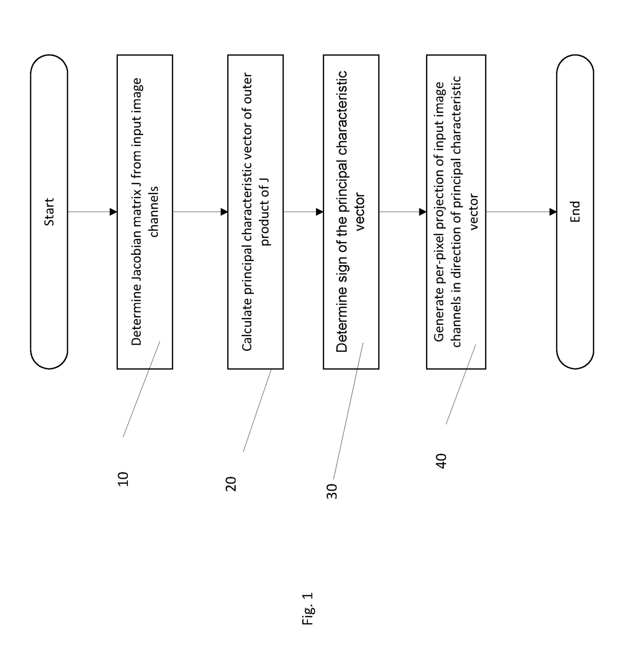
The present invention provides a method and system for generating an output image from a plurality of input image channels. The method involves determining a Jacobian matrix for the input image channels, calculating the principal characteristic vector of the Jacobian matrix, setting the sign of the principal characteristic vector, and generating the output image as a per-pixel projection of the input channels in the direction of the principal characteristic vector. The system includes an input to access the input image channels, a processor to execute computer program code for the method, and a look-up-table to map between a unique input image vector and a principal characteristic vector. The technical effect of the invention is to provide a more efficient and accurate method for generating output images from multiple input image channels.

Problems solved by technology

However, the situation is not straightforward when, for example, the images are captured outside the visible electro-magnetic spectrum, or when more than three channels (also known as dimensions) are captured.
The problem with this approach is that information from additional modalities, such as infra-red and ultra-violet, would be lost.
Unfortunately, the derived gradient field in this approach is often non-integrable.
Because the gradient field reintegration problem (of non-integrable fields) is inherently ill-posed, derivative domain techniques will always hallucinate detail in the fused image that wasn't present in the original image.
Unfortunately, this additional step can produce unnatural contouring and edge effects.

Method used


Image

  • Method and system for generating an output image from a plurality of corresponding input image channels
  • Method and system for generating an output image from a plurality of corresponding input image channels
  • Method and system for generating an output image from a plurality of corresponding input image channels

Examples


Embodiment Construction

[0074]In the following description, I(x,y) is used to denote the xth, yth pixel of an n×m vector image. Each pixel has N planes. For example if I(x,y) was a colour image that is defined with respect to the red, green and blue (RGB) colour space, the pixel would be an RGB vector: [R G B]. If the image also contained an image plane that was NIR (near-infrared), or a NIR image was associated with the RGB one, then each pixel would be a 4-vector: [R G B NIR].

[0075]As will be appreciated, each plane may be a channel of a single image or may be from data of images on the same subject from different sources.

[0076]To understand the derivative structure of an image it is differentiated, in x and y directions, in each of the N image planes. This gives N*2 (x and y derivatives for each of the N image planes) and this is summarized in the N×2 Jacobian matrix J:

J=[δI1δXδI1δYδI2δXδI2δY⋮⋮δINδXδINδY](1)

[0077]In the SW approach described above, a single equivalent derivative was sought that best app...


PUM


Abstract

A method and system for generating an output image from a plurality, N, of corresponding input image channels is described. A Jacobian matrix of the plurality of corresponding input image channels is determined. The principal characteristic vector of the outer product of the Jacobian matrix is calculated. The sign associated with the principal characteristic vector is set whereby an input image channel pixel projected by the principal characteristic vector results in a positive scalar value. The output image as a per-pixel projection of the input channels in the direction of the principal characteristic vector is generated.

Description

FIELD OF THE INVENTION[0001]The present invention relates to a method and system for generating an output image from multi-channel image data such as image data for multiple spectra and / or multiple sensors.BACKGROUND TO THE INVENTION[0002]There are many applications where multiple images or image channels are fused to form a single summary greyscale or colour output. These include computational photography (e.g. RGB-NIR), multispectral photography, diffusion tensor imaging (medical), and remote sensing.[0003]A multitude of different devices capture images that are then displayed on monitors or other display devices. Ultimately, the majority are interpreted, or simply enjoyed, by human observers. To go from a captured image to a visualised image in some cases is straightforward: images captured with an RGB colour camera need only be colour-corrected in order to display an image that is perceptually close to the original scene. However, the situation is not straightforward when, for e...

Claims


Application Information

Patent Timeline
IPC IPC(8): G06T5/50G06T5/00G06T7/13G06T3/20G06T3/00H04N9/31
CPCG06T5/50G06T5/002G06T7/13G06T3/20G06T3/0012H04N9/3179G06T2207/20221G06T2207/20028G06T2207/20192G06T2207/10036G06T2207/10048H04N5/265G06T5/70G06T3/04
Inventor FINLAYSON, GRAHAMHAYES, ALEX
Owner APPLE INC
Learn More