
Vehicle sun visor

a technology for sun visors and vehicles, applied in sun visors, vehicle components, electric/fluid circuits, etc., can solve problems such as possible conduction failures and flickering of illumination lamps

Active Publication Date: 2018-12-20
YAZAKI CORP
View PDF0 Cites 11 Cited by
  • Summary
  • Abstract
  • Description
  • Claims
  • Application Information

AI Technical Summary

Benefits of technology

The present invention aims to solve the problem of an elastically deforming contact part of a terminal deforming due to interference with a contact part of an arm, which can cause flickering of an illumination lamp during lighting. The invention provides a solution in the form of a sun visor for vehicles that prevents the deformation of the terminals and ensures proper functioning of the illumination system.

Problems solved by technology

However, in the conventional vehicle sun visor 1, when assembling the housing 7a of the connector 7 to the mounting recess portion 5b of the mounting bracket 5 to which the support shaft 2 is assembled, unless the support shaft 2 is in a correct position, a plate-shaped spring portion 8a of the terminal 8 may be deformed due to the interference of the columnar conductor end portion 3a, resulting in a possible conduction failure.
Thus, the illumination lamp may flicker at the time of lighting.

Method used


Image

  • Vehicle sun visor
  • Vehicle sun visor
  • Vehicle sun visor

Examples


Embodiment Construction

[0030]In the following detailed description, for purposes of explanation, numerous specific details are set forth in order to provide a thorough understanding of the disclosed embodiments. It will be apparent, however, that one or more embodiments may be practiced without these specific details. In other instances, well-known structures and devices are schematically shown in order to simplify the drawing.

[0031]Description will be hereinbelow provided for embodiments of the present invention by referring to the drawings. It should be noted that the same or similar parts and components throughout the drawings will be denoted by the same or similar reference signs, and that descriptions for such parts and components will be omitted or simplified. In addition, it should be noted that the drawings are schematic and therefore different from the actual ones.

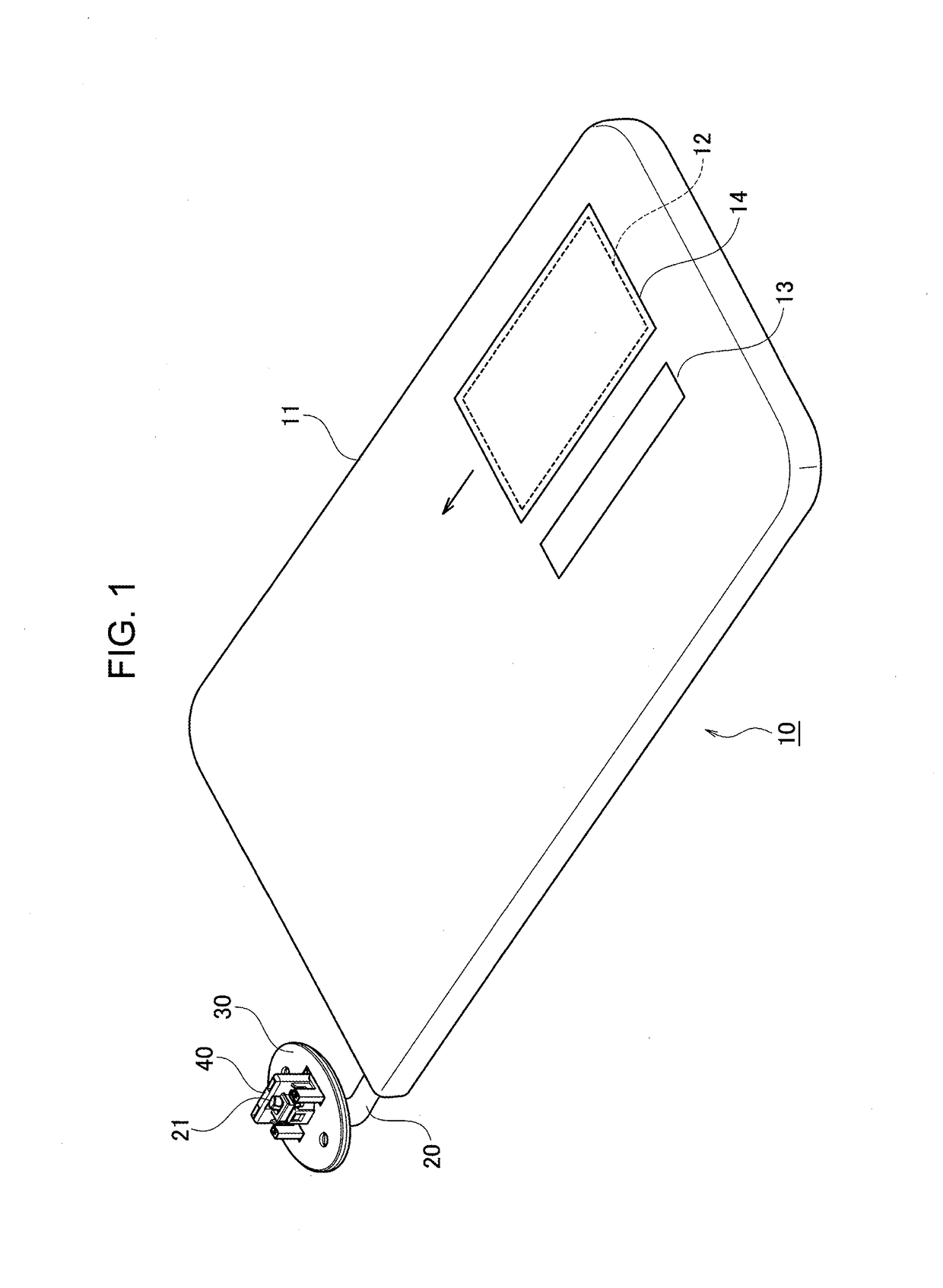
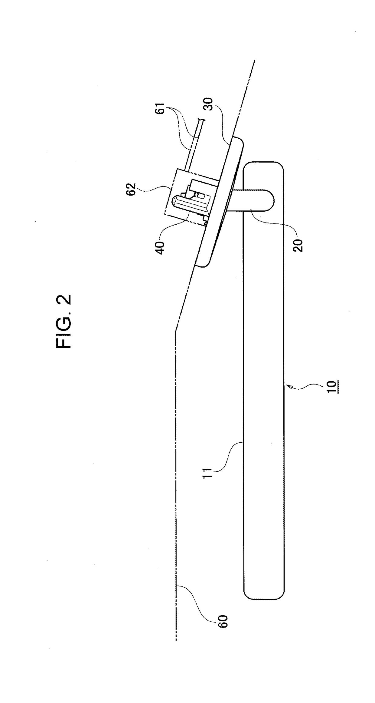
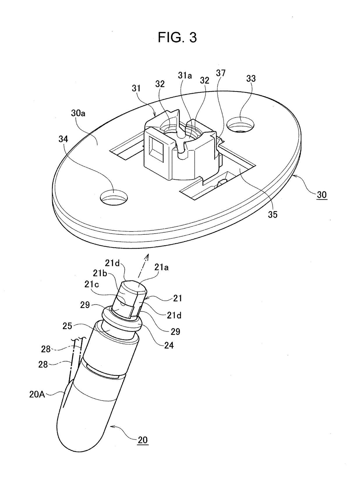
[0032]FIG. 1 is a perspective view of a vehicle sun visor according to one embodiment of the present invention, FIG. 2 is a side view ...


PUM


Abstract

A vehicle sun visor has a sun-visor body including an illumination lamp, a non-conductive arm including a cylindrical-end portion with contact parts of a pair of conductors rotatably holding the sun visor body, a mounting bracket for mounting the arm to a vehicle, and a connector detachably attached to the mounting bracket and including a pair of terminals each having a contact portion to contact with a corresponding contact part of the pair of conductors. An arm-supporting portion of the mounting bracket rotatably supports a cylindrical-end-portion side of the arm. The contact parts of the pair of conductors are in arcuate-plate shape and provided with a cutout on an outer-peripheral surface of the cylindrical-end portion exposed outside the arm-supporting portion. A terminal-fixing portion provided in a housing of the connector fix a base portion of each contact portion, and a terminal-support portion supports a free end of each contact portion.

Description

CROSS REFERENCE TO RELATED APPLICATIONS[0001]This application claims the priority of Japanese Patent Application No. 2017-120273, filed on Jun. 20, 2017, the entire content of which are incorporated herein by reference.BACKGROUNDTechnical Field[0002]The present invention relates to a vehicle sun visor with illumination arranged in the vicinity of an upper end of a front window of a front seat of a vehicle.Related Art[0003]A vehicle sun visor of this type is disclosed in JP 2011-230559 A. As shown in FIG. 11, the vehicle sun visor 1 includes a non-conductive support shaft (arm) 2 for rotatably holding a sun visor body (not shown), a mounting bracket 5 for mounting the support shaft 2 to a ceiling of a vehicle cabin (not shown), and a connector 7 detachably assembled to the mounting bracket 5 and having a pair of terminals 8 and 8 for supplying electric power.[0004]A pair of conductors 3 and 3 extending in parallel is arranged inside the support shaft 2. Each columnar conductor end po...

Claims


Application Information

Patent Timeline
Patent Type & Authority Applications(United States)
IPC IPC(8): B60J3/02B60Q3/252
CPCB60J3/0217B60Q3/252B60J3/02B60Q3/51B60R16/03B60J3/0221
Inventor KAWASHIMA, KENICHI
Owner YAZAKI CORP
Learn More