Camera module and electronic device including same

Active Publication Date: 2018-12-20
SAMSUNG ELECTRONICS CO LTD
View PDF2 Cites 11 Cited by
  • Summary
  • Abstract
  • Description
  • Claims
  • Application Information

AI Technical Summary

Benefits of technology

[0031]The reflection unit may be a mirror in which reflection surfaces of two mirrors are orthogon

Problems solved by technology

In this way, it is difficult to embed elements for realizing bi-directional photographing including general photographing of photogra

Method used


Image

  • Camera module and electronic device including same
  • Camera module and electronic device including same
  • Camera module and electronic device including same

Examples


embodiment 1

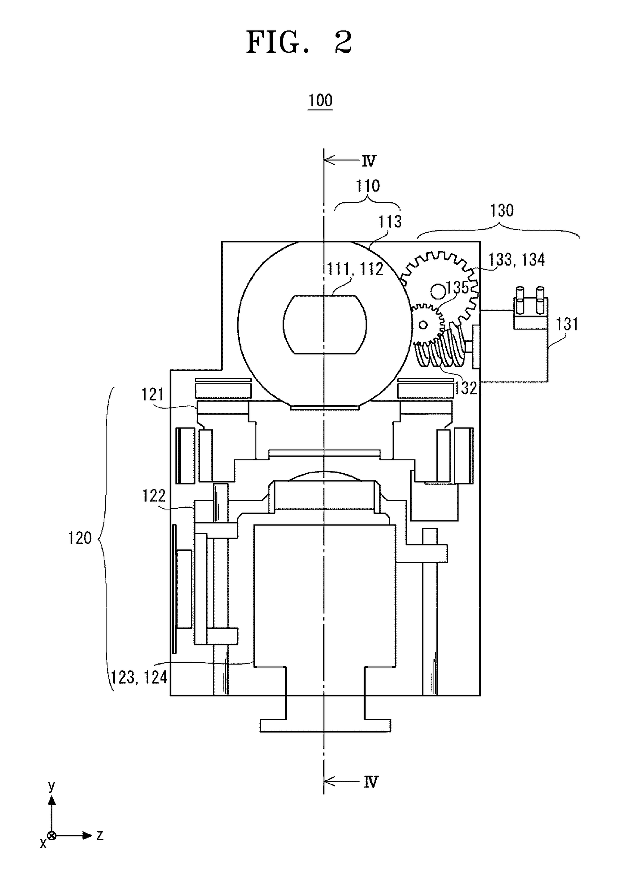
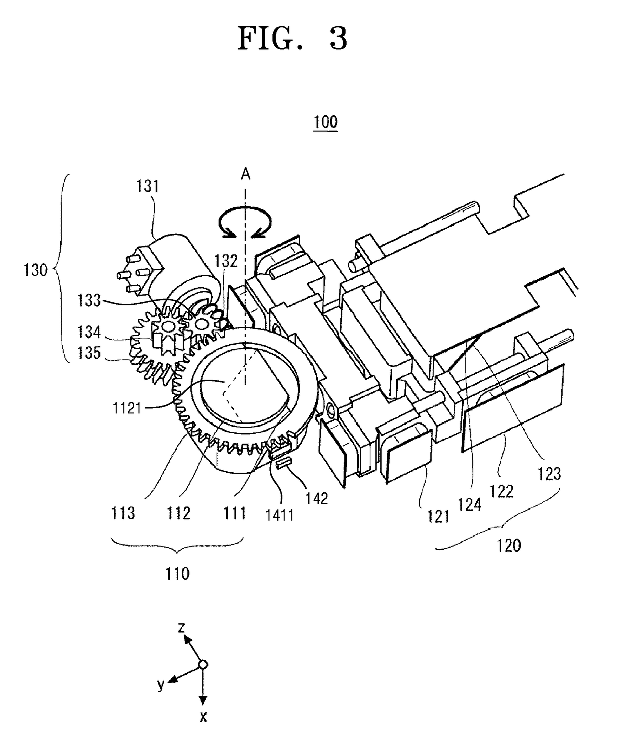
[0058]Hereinafter, embodiments of the present disclosure will be described with reference to the accompanying drawings. FIG. 2 is a front perspective view of one example of a configuration of a camera module according to Embodiment 1 of the preset disclosure. FIGS. 3 and 5 are perspective views of one example of a configuration of a camera module according to Embodiment 1 of the preset disclosure. FIGS. 4 and 6 are cross-sectional views taken along line IV-IV of FIG. 2 illustrating an example of a configuration of a camera module according to Embodiment 1 of the present disclosure. In each of the drawings, a first photographing direction (a direction in which scenery or the like is photographed) and a second photographing direction (a selfie photographing direction) that is opposite to the first photographing direction are referred to as an X-axis direction, and a direction perpendicular to the first photographing direction (a direction of a light-receiving unit 120) is referred to ...

embodiment 2

[0100]In Embodiment 1, the reflection unit is configured using a complex prism in which reflection surfaces of two prisms face each other. However, in Embodiment 2, an example in which refraction characteristics of the two prisms are different from each other, will be described.

[0101]FIG. 10 is a cross-sectional view of an example of a reflection unit of a camera module according to Embodiment 2. In FIG. 10, the same reference numerals are used for the same elements as those of FIGS. 2 to 6, and a description thereof will be omitted. In FIG. 10, the reflection unit 110 includes a prism 311, a prism 312, and a gear 113.

[0102]The first prism 311 and the second prism 312 are made of light-transmitting materials and have first and second reflection surfaces 3113 and 3123, respectively, on which light is reflected from an inclined surface.

[0103]The first prism 311 is a prism that reflects light incident from the side located in the first photographing direction in a direction of the ligh...

embodiment 3

[0110]In Embodiment 3, first and second reflection surfaces of two, first and second prisms are orthogonal to each other and are placed parallel to each other and undergo parallel translation in a direction of a light-receiving unit and in a direction perpendicular to photographing direction so that light is selected from one of a first photographing direction and a second photographing direction and is reflected in the direction of the light-receiving unit.

[0111]FIGS. 11 and 12 are perspective views illustrating an example of a configuration of a camera module according to Embodiment 3. Also, FIG. 13 is a side view illustrating an example of the configuration of the camera module according to Embodiment 3. In FIGS. 11 through 13, the same reference numerals are used for the same elements as those of FIGS. 2 through 6, and a description thereof will be omitted.

[0112]In FIGS. 11 to 13, a camera module 400 includes a reflection unit 410, a light-receiving unit 120, and a parallel move...


PUM


Abstract

Provided is a camera module capable of selectively capturing an image in a first photographing direction or in a second photographing direction opposite to the first photographing direction. The camera module includes: a reflection part that is movable between a first location, at which light incident from a side located in the first photographing direction is reflected in a direction perpendicular to the first photographing direction, and a second location, at which light incident from a side located in the second photographing direction is reflected in a direction perpendicular to the first photographing direction; and a light reception part configured to capture an image by converting the light, which has been reflected by the reflection part, into an electrical signal, wherein, during the movement of the reflection part, the thickness of the reflection part can be constantly maintained in the first photographing direction.

Description

CROSS-REFERENCE TO RELATED APPLICATIONS AND CLAIM OF PRIORITY[0001]This application is a 371 National Stage of International Application No. PCT / KR2016 / 014438 filed Dec. 9, 2016, which claims priority to Japanese Patent Application No. JP 2015-254078, filed on Dec. 25, 2015 and Korean Patent Application No. KR 10-2016-0135260, filed on Oct. 18, 2016, the disclosures of which are herein incorporated by reference in their entirety.BACKGROUND1. Field[0002]The present disclosure relates to a camera module and an electronic device including the same, and more particularly, to a camera module with a slim shape_and an electronic device including the camera module.2. Description of Related Art[0003]Recently, electronic devices having a camera module mounted thereon, for example, portable communication terminal equipment, having a function of photographing a landscape or person and a self-timer photographing function (hereinafter, referred to as “selfie photographing” allowing a photographer...

Claims


Application Information

Patent Timeline
IPC IPC(8): G02B27/64H04M1/02H04N5/232H04N5/225
CPCG02B27/646H04M1/02H04N5/23287H04N5/2254H04N2201/0084H04M1/0264H04M2250/52G03B5/06G03B29/00G03B37/04H04N23/58H04N23/54H04N23/55H04N23/687G02B27/642
Inventor MASAHIRO, SHIRONO
Owner SAMSUNG ELECTRONICS CO LTD
Why Eureka
Try Eureka