Rotary suction device

a rotary suction device and suction cup technology, applied in the direction of suction cups, machine supports, fastening means, etc., can solve the problems of large and thick conventional suction disks, inconvenient movement of pushing handles, and insufficient space for pushing handles, so as to strengthen the stability of elastic components

Active Publication Date: 2016-08-02
CHICONY ELECTRONICS
View PDF8 Cites 12 Cited by
  • Summary
  • Abstract
  • Description
  • Claims
  • Application Information

AI Technical Summary

Benefits of technology

[0011]The effect of attachment of the rotary suction device of the instant disclosure is produced by rotating the upper cover to have the suction disk had an axial displacement relative to the upper cover. Comparing to conventional suction disk devices, the rotary suction device does not require any conventional handle, has simple manufacturing process, and saves the production cost. Further, the rotary suction device of the instant disclosure can be designed as a thinner shape to decrease volume. In addition, users can conveniently practice the operation of the rotary suction device by only one hand.
[0013]According to an embodiment, the central pivot includes an inner trough which is around the elastic component. An end of the elastic component is against a bottom of the inner trough, which can prevent the elastic component from shifting and can strengthen the connection between the elastic component and the upper cover.
[0019]According to an embodiment, the base further includes a positioning column disposed in the central circular trough, and the elastic component can be a spring which is around the positioning column in order to strengthen the stability of the elastic component.

Problems solved by technology

However, conventional suction disk devices have some issues described below.
First, the movement of pushing handles requires enough space according to the size of handles.
Therefore, conventional suction disks are usually large and thick, and the operations are complicated.
Second, the operation for operating conventional suction disk devices to have the suction disk moved and to produce the effect of attachment requires that a user press the suction disk by one hand, and push the handle by the other hand.
The requirement for operating conventional suction disk devices is not convenient for users.
Comparing to conventional suction disk devices, the rotary suction device does not require any conventional handle, has simple manufacturing process, and saves the production cost.

Method used


Image

  • Rotary suction device
  • Rotary suction device
  • Rotary suction device

Examples


Embodiment Construction

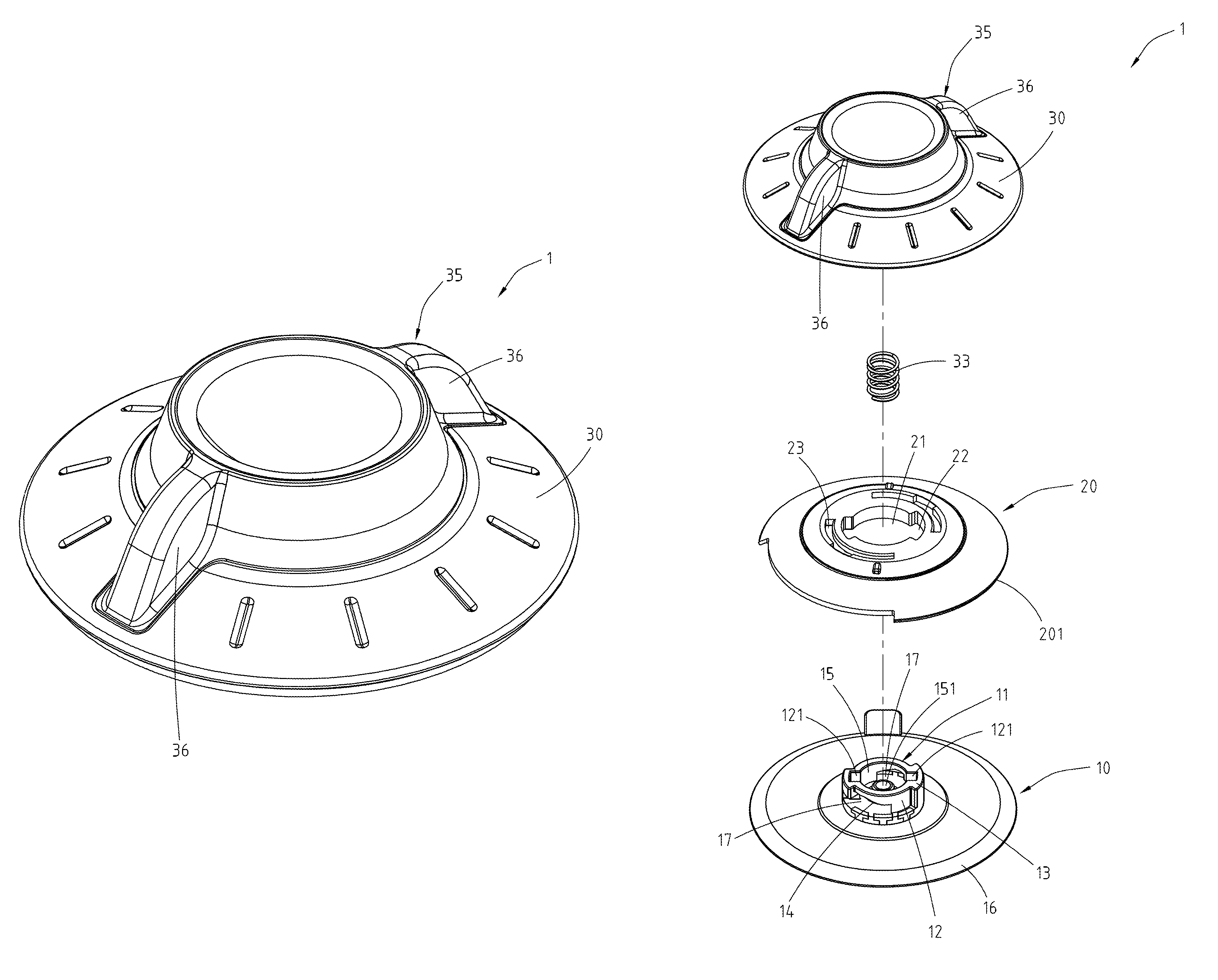
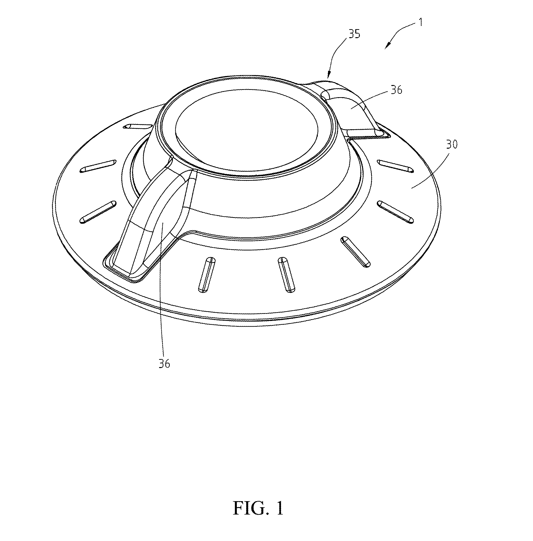
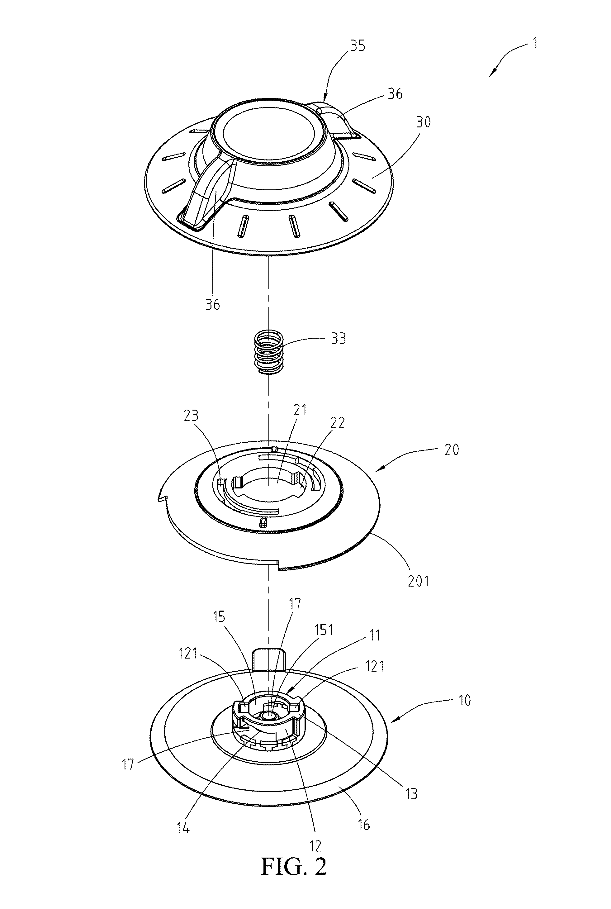
[0031]Referring to FIG. 1 to FIG. 4, an embodiment of the instant disclosure provides a rotary suction device 1 which includes a suction disk 10, a middle cover 20, and an upper cover 30. In the embodiment, the suction disk 10 includes a base 11 and a soft disk 16 connected to the base 11. The soft disk 16 may be composed of soft materials like rubber or silicone. The base 11 may be composed of hard materials like plastic. The base 11 is disposed on the center of a side of the soft disk 16. The soft disk 16 and the base 11 can be manufactured as one piece (e.g., in a manner of in-mold forming).

[0032]The base 11 includes a peripheral wall 12, two guide blocks 13 protruding from the peripheral wall 12, two inclined surfaces 14 disposed in the peripheral wall 12, and a central circular trough 15 formed in an inner side of the base 11. In the embodiment, the peripheral wall 12 has a roughly circle shape and surrounds to form the central circular trough 15. The two guide blocks 13 are sy...


PUM


Abstract

The rotary suction device includes a suction disk, a middle cover, and an upper cover. The suction disk includes a base and a soft disk. The base includes a peripheral wall, a guide block, an inclined surface, and a central circular trough. The middle cover includes a central through hole around the peripheral wall and a guide trough. The guide trough is around the guide block, and the middle cover is capable of axial displacement relative to the suction disk. The upper cover includes a central pivot, a sliding block, and an elastic component. The central pivot is accommodated in the central circular trough such that the upper cover is capable of rotating relative to the suction disk. The elastic component is disposed between the upper cover and the suction disk. The sliding block is forced to against the inclined surface by the elastic force of the elastic component.

Description

CROSS-REFERENCES TO RELATED APPLICATIONS[0001]This non-provisional application claims priority under 35 U.S.C. §119(a) on Patent Application No. 103134677 filed in Taiwan, R.O.C. on 2014 Oct. 3, the entire contents of which are hereby incorporated by reference.BACKGROUND[0002]1. Technical Field[0003]The instant disclosure relates to a suction device, and more particularly, to a rotary suction device.[0004]2. Related Art[0005]Ordinarily, attaching an object to a surface of another object can be practiced by using a suction disk. Suction disks, for example, can utilized for attaching a hook, a rack or a handle to a surface of a wall, or attaching an event data recorder (EDR) or a navigation device to a dashboard or a windshield of a vehicle. The use of suction disks has lots of advantages such as making no damages to surfaces to which objects attach, having easy assembly process, and having ability to conveniently change attaching locations.[0006]The conventional suction disk device a...

Claims


Application Information

Patent Timeline
Patent Type & Authority Patents(United States)
IPC IPC(8): F16B47/00F16M13/02
CPCF16B47/006F16M13/022F16B47/00
Inventor HUANG, WEI-CHENGTSAI, MEI-YIHUANG, CHUN-YULIN, CHANG-YI
Owner CHICONY ELECTRONICS
Why Eureka
Try Eureka