Laminated Ultra-High Vacuum Forming Device

a technology of ultra-high vacuum and creating device, which is applied in the direction of machine/engine, positive displacement liquid engine, particle separator tube, etc., can solve the problems of unnecessarily large and heavy scale of the entire device, and achieve the effect of improving the efficiency of the exhaust process

Active Publication Date: 2017-05-11
NAT INST OF INFORMATION & COMM TECH
View PDF5 Cites 11 Cited by
  • Summary
  • Abstract
  • Description
  • Claims
  • Application Information

AI Technical Summary

Benefits of technology

[0046]According to the present invention, it is possible to provide the ultra-high vacuum creating device which includes the ion pump whose size in the central-axis direction is further reduced while maintaining the basic performances of the conventional ion pump such as the light weight, the efficiency, and the exhaust property.
[0047]The ion pump 100 has a thin shape (preferably, a disc shape) in the present invention, and accordingly, can also be mounted in, for example, a vacuum chamber with few margin in the mounting space such as the lens barrel of the electron gun. In addition, it is also possible to mount the heating and non-evaporating getter pump 200 having an excellent gettering performance of hydrogen in an ultra-high vacuum space and the sublimation pump 300 having an excellent gettering performance in a low vacuum space as well as the ion pump 100 combinedly in the vacuum chamber with a margin in the mounting space. When a plurality of pump units are connected in tandem with each other in this manner, the exhaust amount and exhaust characteristics thereof can be enhanced and adjusted if necessary. Accordingly, the ultra-high vacuum creating device of the present invention has, for example, a start-up vacuum level of 10−4 Pa to 10−3 Pa and can improve an ultimate vacuum level up to 10−9 Pa to 10−8 Pa.
[0048]The ultra-high vacuum creating device of the present invention can be suitably applied to, for example, an ion beam processing device in which large gases are released from a sample, various processing devices, an ionized gas generation device, an ion source generation device, and the like. In addition, the ultra-high vacuum creating device of the present invention can also be suitably applied to, for example, a synchrotron radiation facility which requires more stable ultra-high vacuum environment, an ion trap, an atomic clock, and the like.

Problems solved by technology

In this manner, the exhaust device has a large-scale structure, a chamber housing the device becomes bulky, and as a result, there is a problem that the entire device scale becomes unnecessarily larger and heavier.

Method used


Image

  • Laminated Ultra-High Vacuum Forming Device
  • Laminated Ultra-High Vacuum Forming Device
  • Laminated Ultra-High Vacuum Forming Device

Examples


Embodiment Construction

[0070]Hereinafter, embodiments of the present invention will be described with reference to the drawings. The present invention is not limited to the embodiments described below, but includes amendments thereto made appropriately by those skilled in the art to the extent obvious.

[0071]In the specification of the present application, a “plate shape” means a shape formed to have the width longer than the thickness. The plate shapes include not only a disk shape but also a polygonal plate shape such as a square plate shape.

[0072]In the specification of the present application, a “ring shape” means a shape formed to have an opening at the center thereof. The ring shapes include not only a circular ring shape but also a polygonal ring shape such as a square ring shape.
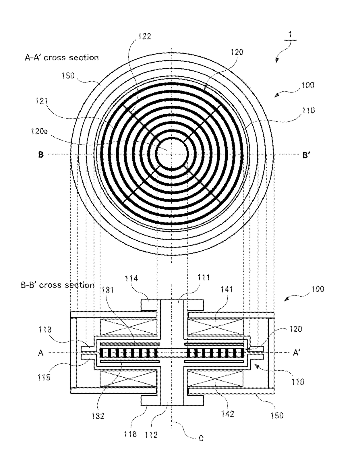
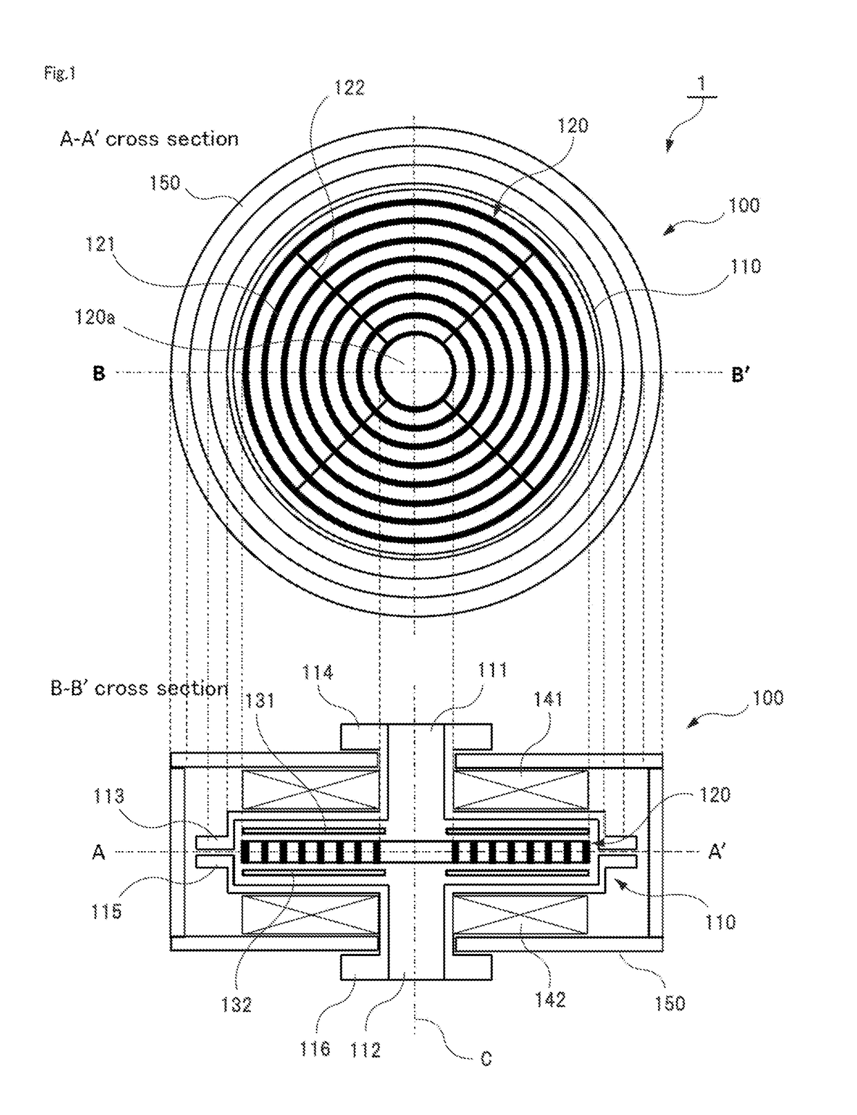
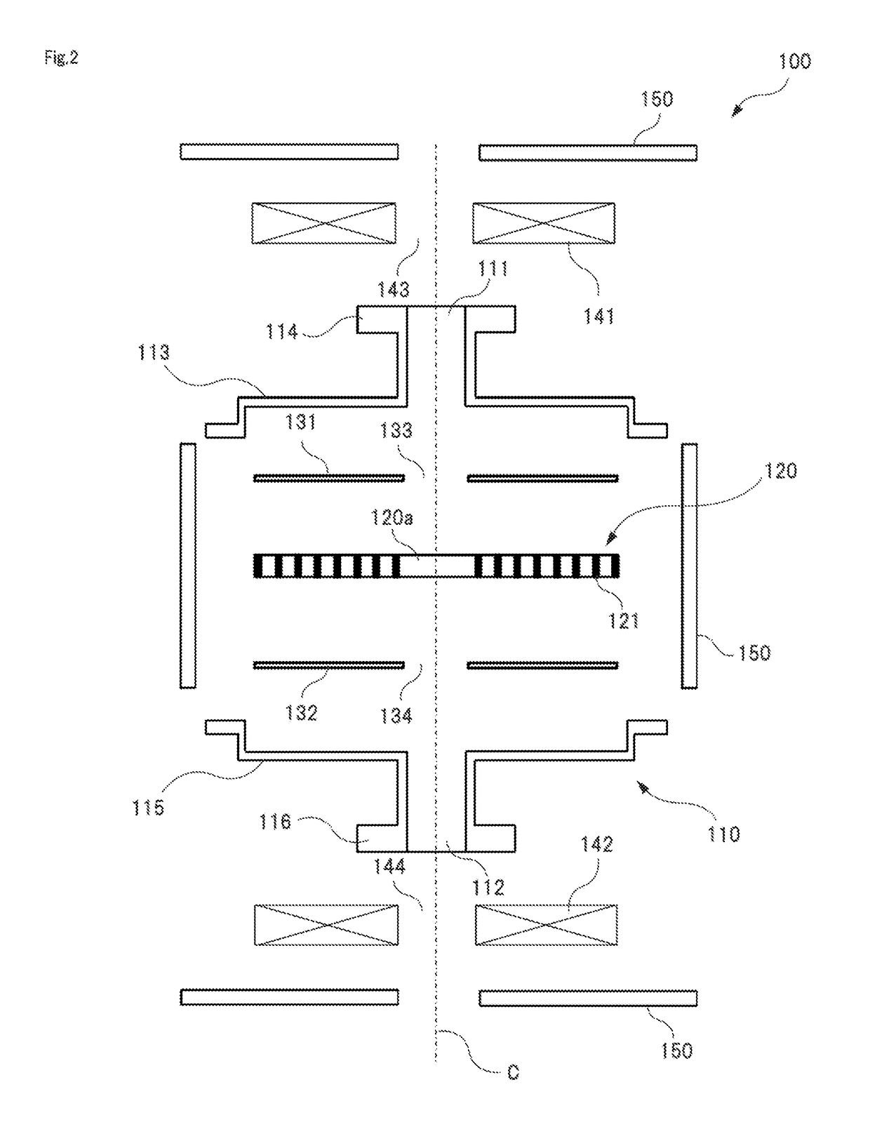
[0073][1. Ion Pump]

[0074]An ultra-high vacuum creating device 1 according to the present invention is configured to include an ion pump 100. FIGS. 1 to 9 illustrate configuration examples of the ion pump 100 included in the...


PUM


Abstract

Provided is an ultra-high vacuum forming device containing an ion pump having a compact size in the central axis direction. The ultra-high vacuum forming device (1) is provided with at least one ion pump (100). The ion pump (100) is provided with: a casing (110) having at least one opening (111, 112); a board-shaped electrode group (120) formed by means of a central opening (120a) being formed along a predetermined central axis (C) disposed within the casing (110), and a plurality of electrodes (121) being joined with spaces therebetween; a pair of board-shaped electrodes (131, 132) having a different polarity than that of the electrode group (120) and that are disposed at positions sandwiching both sides of the electrode group (120) within the casing (110); and a pair of board-shaped magnets (141, 142) disposed at positions sandwiching both sides of the pair of board-shaped electrodes (131, 132).

Description

TECHNICAL FIELD[0001]The present invention relates to an ultra-high vacuum creating device. To be specific, the ultra-high vacuum creating device of the present invention includes at least one ion pump. In addition, the ultra-high vacuum creating device of the present invention is configured to include another ion pump, a heating and non-evaporating getter pump and a sublimation pump arbitrarily stacked on the ion pump according to an application, and accordingly, an exhaust characteristic thereof can be optimized according to the application.BACKGROUND ART[0002]Recently, an ultra-high vacuum technique has been regarded as important along with remarkable development of a nanotechnology and an ultra-precision measurement technique. For example, a surface of a semiconductor is easily contaminated by gas molecules, and conventionally, there has been a need of maintaining the semiconductor in an ultra-high vacuum state under 10−5 Pa or lower to keep the clean semiconductor surface. In a...

Claims


Application Information

Patent Timeline
Patent Type & Authority Applications(United States)
IPC IPC(8): H01J41/12
CPCH01J41/12H01J41/18H01J41/20F04B37/14
Inventor TANAKA, SHUKICHI
Owner NAT INST OF INFORMATION & COMM TECH
Why Eureka
Try Eureka