

Vibration controller
a vibration controller and controller technology, applied in the field of vibration controllers, can solve the problems of reducing the quality factor of parametric resistors, the inability to sufficiently dampen vibration in objects of control, and the inability of parametric resistors to reduce quality factors, so as to achieve the effect of increasing the q of resonance and effectively reducing the vibration energy of objects of control
- Summary
- Abstract
- Description
- Claims
- Application Information
AI Technical Summary
Benefits of technology
Problems solved by technology
Method used
Image

Examples
first embodiment
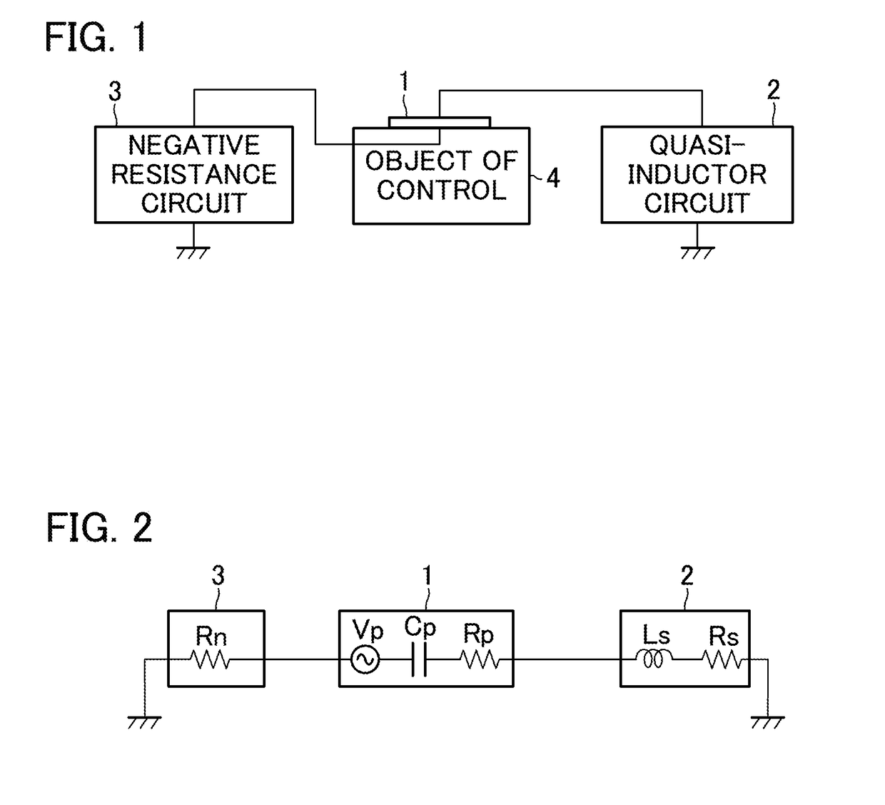
[0017]FIG. 1 is a block diagram illustrating a configuration of a vibration controller according to a first embodiment of this invention. As illustrated in FIG. 1, the vibration controller according to the present embodiment includes: a piezoelectric element 1 fixed to a surface of an object of control (an object in which vibration is to be controlled) 4, such as a musical instrument or a speaker housing; a quasi-inductor circuit 2 provided between one of the two electrodes of the piezoelectric element 1 and a grounding wire; and a negative resistance circuit 3 provided between the other electrode of the piezoelectric element 1 and a grounding wire. Preferably, the piezoelectric element 1 is fixed to the object of control 4, at position where maximum distortion occurs in generation of natural vibration in the object of control 4.
[0018]FIG. 2 is a circuit diagram illustrating a configuration of an equivalent circuit of the vibration controller illustrated in FIG. 1. As illustrated in...
second embodiment
[0046]FIG. 6 is a circuit diagram illustrating a configuration of a quasi-inductor circuit 2B used in a vibration controller according to a second embodiment of this invention. The quasi-inductor circuit 2B differs from the quasi-inductor circuit 2 of the first embodiment as follows: the quasi-inductor circuit 2B includes a source follower 23B as a buffer amplifier instead of the voltage follower 23; the resistors R203 and R204 are omitted from the quasi-inductor circuit 2B; and the quasi-inductor circuit 2B additionally includes a variable resistor R207, a resistor R208, a resistor R209, an NPN transistor Tna, a PNP transistor Tpa, a DC power supply Vb3, and a DC power supply Vb4. A part of a first current feedback amplifier circuit is formed by the variable resistor R207, the resistor R208, the NPN transistor Tna, and the power supply Vb3. A part of a second current feedback amplifier circuit is formed by the variable resistor R207, the resistor R209, the PNP transistor Tpa, and t...
third embodiment
[0058]FIG. 7 is a circuit diagram illustrating a configuration of a quasi-inductor circuit 2C used in a vibration controller according to a third embodiment. The quasi-inductor circuit 2C differs from the quasi-inductor circuit 2B of the second embodiment in the following: the power supply Vb1 is omitted from the quasi-inductor circuit 2C; and the quasi-inductor circuit 2C additionally includes an inverting amplifier circuit 26C, a PNP transistor Tpd, an NPN transistor Tnd, a resistor R211, and a resistor R212.
[0059]The resistor R211 is provided between the positive power supply Vcc and the emitter of the PNP transistor Tpd. The collector of the PNP transistor Tpd is connected to the collector of the NPN transistor Tna. The base of the PNP transistor Tpd is connected to the collector of the PNP transistor Tpd and the base of the PNP transistor Tp. The PNP transistor Tpd and the PNP transistor Tp form a current mirror circuit. In the current mirror circuit, a current of the same valu...
PUM
 Abstract
Description
Claims
Application Information