
Printable heaters to heat wearables and other articles

a technology of wearables and heaters, applied in the field of improved printable heaters, can solve the problems of difficult to print resistive material layers with appropriate thickness and uniformity using currently available compositions, wires rendering garments uncomfortable, and heaters are relatively high

Inactive Publication Date: 2018-12-20
DUPONT ELECTRONICS INC
View PDF3 Cites 1 Cited by
  • Summary
  • Abstract
  • Description
  • Claims
  • Application Information

AI Technical Summary

Benefits of technology

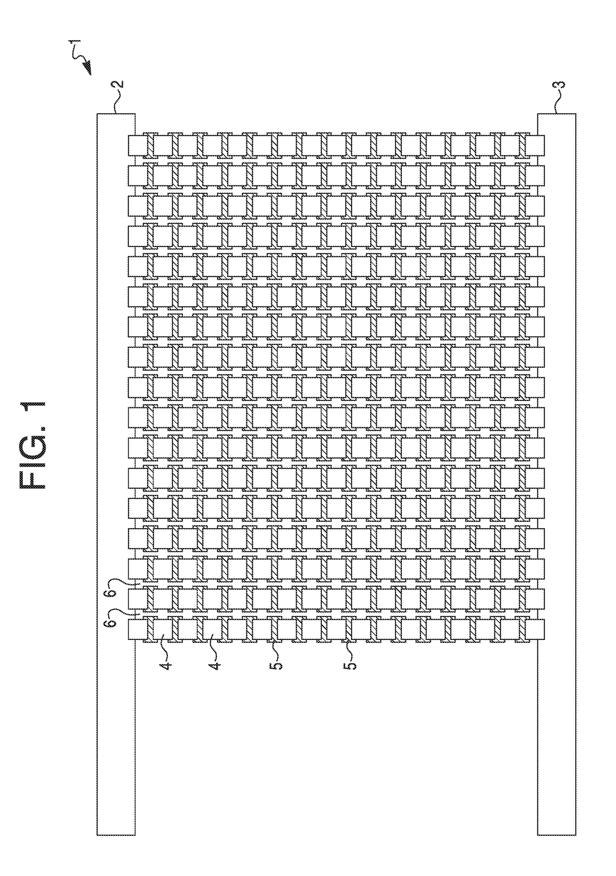
The patent text is describing a heater that is printed on a permeable substrate and can be used in a wearable garment. The invention provides breathability to the heater by allowing air to pass through the separations between the columns. This creates a more comfortable and relaxed feeling for the wearer.

Problems solved by technology

However, they have the disadvantage that the presence of the wires renders the garments uncomfortable.
It is difficult to print a large area resistive material layer with appropriate thickness and uniformity using currently available compositions.
The resistance of such a heater is relatively high and batteries cannot deliver the power needed for a viable heater.
The use of interdigitated electrodes with the large area resistive material can result in a considerable decrease in resistance.
However, there is still the difficulty in printing the large area of resistive material.
And in both of these approaches the large printed resistive material area can result in that portion of the garment not being breathable, i.e., not allowing water vapor transport, and this would be a source of discomfort for the wearer.

Method used


Image

  • Printable heaters to heat wearables and other articles
  • Printable heaters to heat wearables and other articles
  • Printable heaters to heat wearables and other articles

Examples


example 1

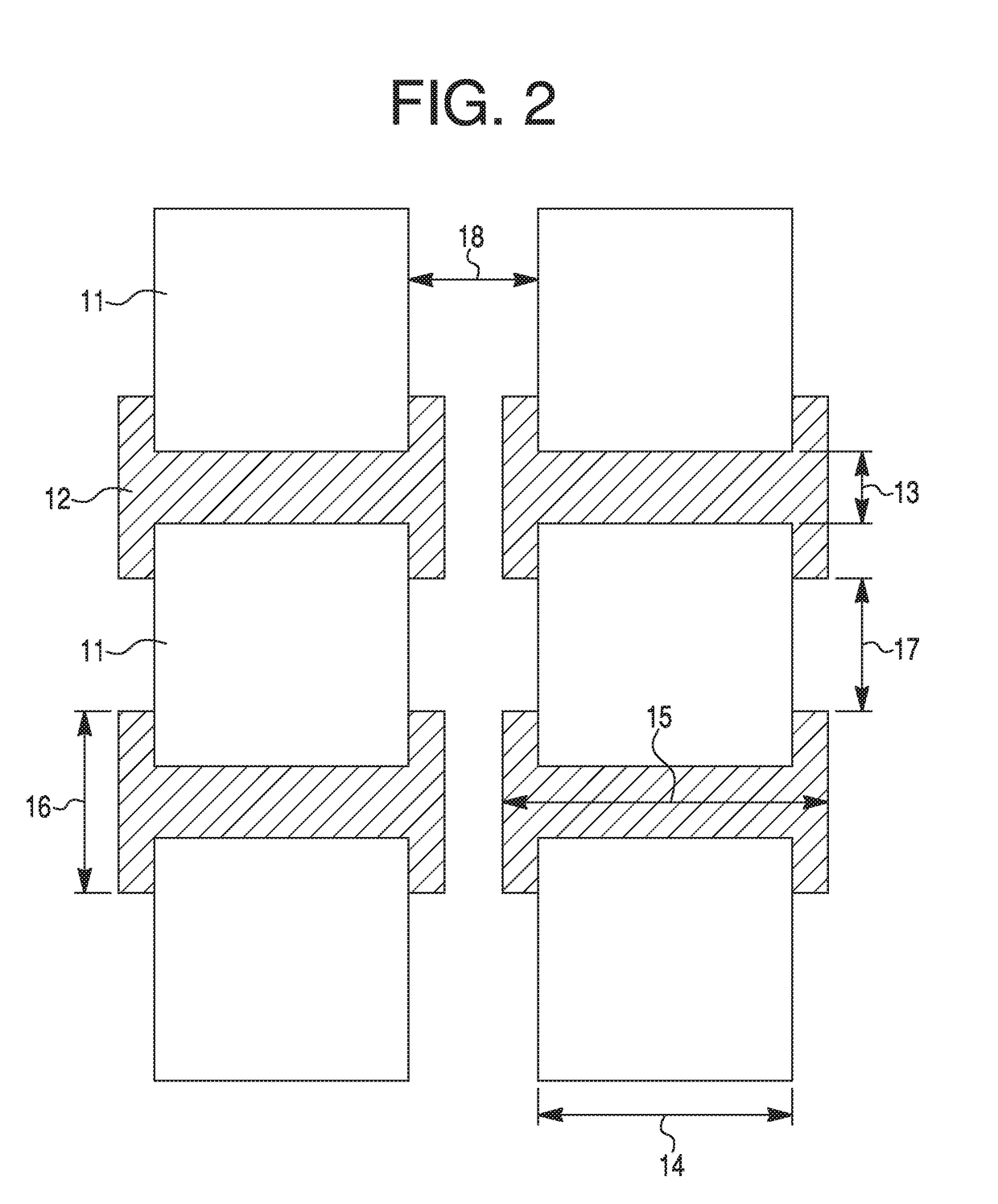
[0053]A heater with the Configuration A shown in FIG. 1 was made and tested. The overall dimensions of the heater were 250 mm in width and 170 mm in height. The heater was printed on a clear thermoplastic polyethylene terephthalate (PET) substrate with a thickness of 0.2 mm. Referring to FIGS. 1 and 2, the printed resistive material rectangles 4 and 11 were made of printed carbon paste (DuPont™ 7105, DuPont Co., Wilmington, Del.) with a sheet resistivity of 22 Ohms / square. The number of resistive rectangles 4 and 11 in each column was nineteen, M=19, and there were forty-eight columns, N=48. There were two identical conductive bus bars 2 and 3, with lengths of 250 mm and widths of 15 mm. There was a 1 mm overlap of the bus bars with the adjacent printed resistive material rectangles. Each column had eighteen electrically conductive printed rectangles 5 and 12. The bus bars and the conductive rectangles were made of printed silver paste (DuPont™ 5025 Silver Conductor, DuPont Co., Wil...

example 2

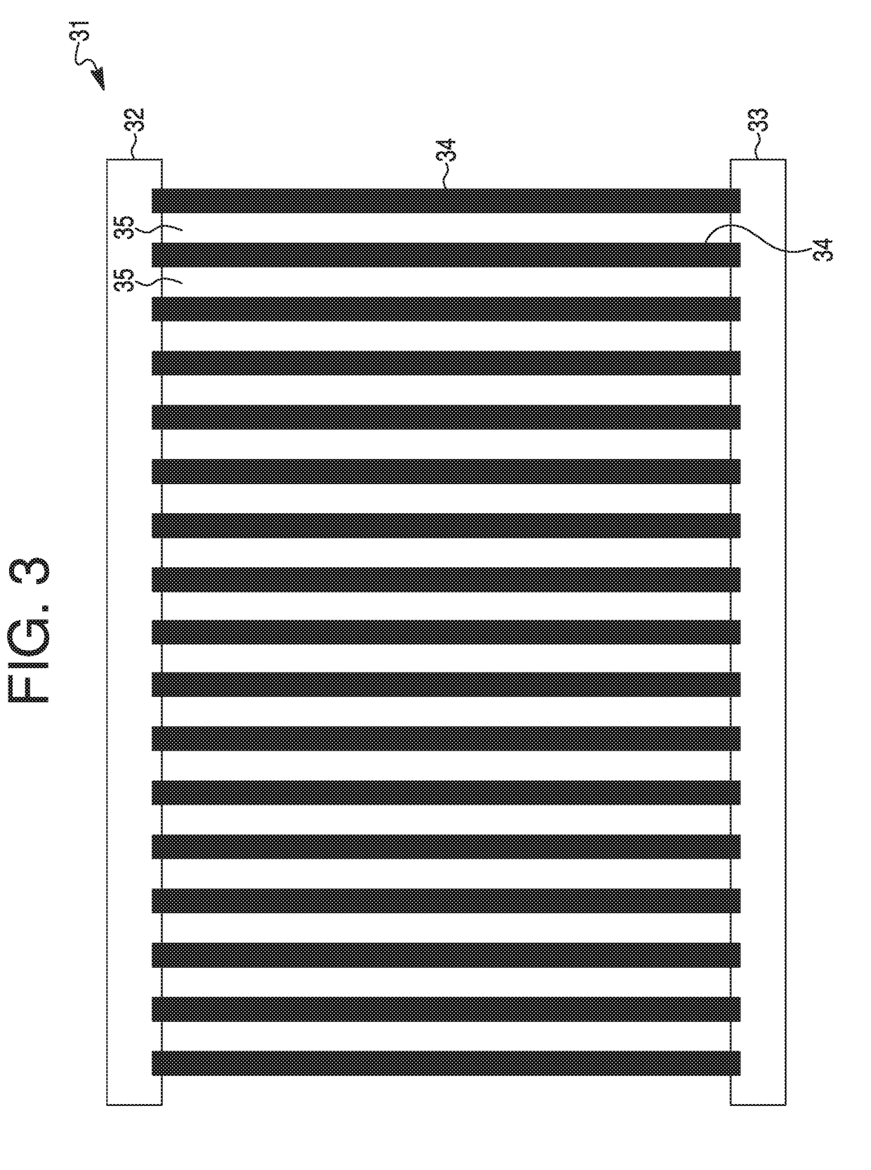
[0056]A heater with the Configuration C was made and tested. The heater was printed on a clear thermoplastic polyethylene terephthalate (PET) substrate with a thickness of 0.2 mm. The printed resistive material columns were made of printed carbon paste (DuPont™ 7105, DuPont Co., Wilmington, Del.) with a sheet resistivity of 22 Ohms / square. There were forty-eight resistive material columns, N=48, and each column had a width W of 4 mm. The lateral distance between columns was 1 mm. There were two identical conductive bus bars with lengths of 250 mm and widths of 15 mm. Each resistive material column overlapped and made electrical contact with the bus bars. There were 18 conductive rectangles spaced uniformly along the length of a column of resistive material. Each conductive rectangle had a width w of 4 mm and length l of 3 mm. The bus bars and the conductive rectangles were made of printed silver paste (DuPont™ 5025 Silver Conductor, DuPont Co., Wilmington, Del.) with resistivity of ...


PUM


Abstract

This invention provides improved printed heaters to heat a variety of articles. The improvement comprises replacing the single large area resistive material layer with columns of a number of small patches of resistive material or of continuous resistive material, i.e., replacing the single large area heater with a number of smaller individual heaters. Printing of the resistive material is facilitated since the area of each resistive material patch is greatly reduced. In addition, some embodiments enable the opportunity to provide a breathable heater for use in wearable garments.

Description

FIELD OF THE INVENTION[0001]This invention is directed to improved printable heaters for use in heating wearable garments, seats and parts of electric automobiles.BACKGROUND OF THE INVENTION[0002]There is a need for heaters to heat articles such as wearable garments, seats and parts of electric automobiles.[0003]There is increasing interest in providing heatable wearable garments. Currently typical commercialized heated garments are heated by resistance wires. These garments have the advantage that the areas between the wires allow the fabric to breathe. However, they have the disadvantage that the presence of the wires renders the garments uncomfortable.[0004]An alternative is to use heaters with printed components which would provide greater comfort to the wearer. In one such version, a component of the heated garment is a layer of resistive material, e.g., carbon, which serves as the resistive heating element between two bus bars. Such a layer could cover a significant portion of...

Claims


Application Information

Patent Timeline
Patent Type & Authority Applications(United States)
IPC IPC(8): H05B3/34
CPCH05B3/342H05B2203/011H05B2203/013H05B2203/017H05B2203/036A41D13/0051H05B3/10H05B3/146H05B3/34H05B2203/029
Inventor LAMONTIA, MARK ALLANMEHDIZADEH, MEHRDAD
Owner DUPONT ELECTRONICS INC
Learn More