Weatherproof electrical enclosure with reinforcement

Active Publication Date: 2019-01-10
HUBBELL INC
View PDF75 Cites 1 Cited by
  • Summary
  • Abstract
  • Description
  • Claims
  • Application Information

AI Technical Summary

Benefits of technology

[0006]The present disclosure provides descriptions of embodiments for ceiling mounted electrical box assemblies used to support relatively heavy electrical fixtures, such as ceiling fans. The present disclosure provides descriptions of ceiling fan kits that incorporate an electrical box assembly of the present disclosure and a ceiling fan. The electrical box assemblies of the present disclosure are made of a non-conductive electrical box and a reinforcement member that provides mechanical strength to support the weight of the electrical fixture and to resist torque or other forces generated when the electrical fixture is operated.
[0007]In one embodiment, the electrical box assembly includes an electrical box and a reinforcement member. The electrical box has a bottom wall with a mounting zone and an open front face. The reinforcement member has a panel and one or more standoffs extending from the panel. The panel is shaped to conform to at least a portion of the bottom wall of the box so that the panel can be positioned within the electrical box adjacent the bottom wall. The one or more standoffs extend toward the front face of the box and include at least one connecting hole configured to receive a fastener of the fixture.
[0008]In another embodiment, the electrical box assembly includes an electrical box, a reinforcement member and a shroud. The electrical box has a bottom wall with a mounting zone and an open front face. The reinforcement member has a pa

Problems solved by technology

In outdoor environments, such fixtures may include a weatherproof housing that limits moisture, dust, pests, and other outdoor hazards from the mechanism and circuitry of the device.
Ceiling fans are relatively heavy, compared with other electrical fixtures, such as lighting fixtures.
In

Method used


Image

  • Weatherproof electrical enclosure with reinforcement
  • Weatherproof electrical enclosure with reinforcement
  • Weatherproof electrical enclosure with reinforcement

Examples


Example

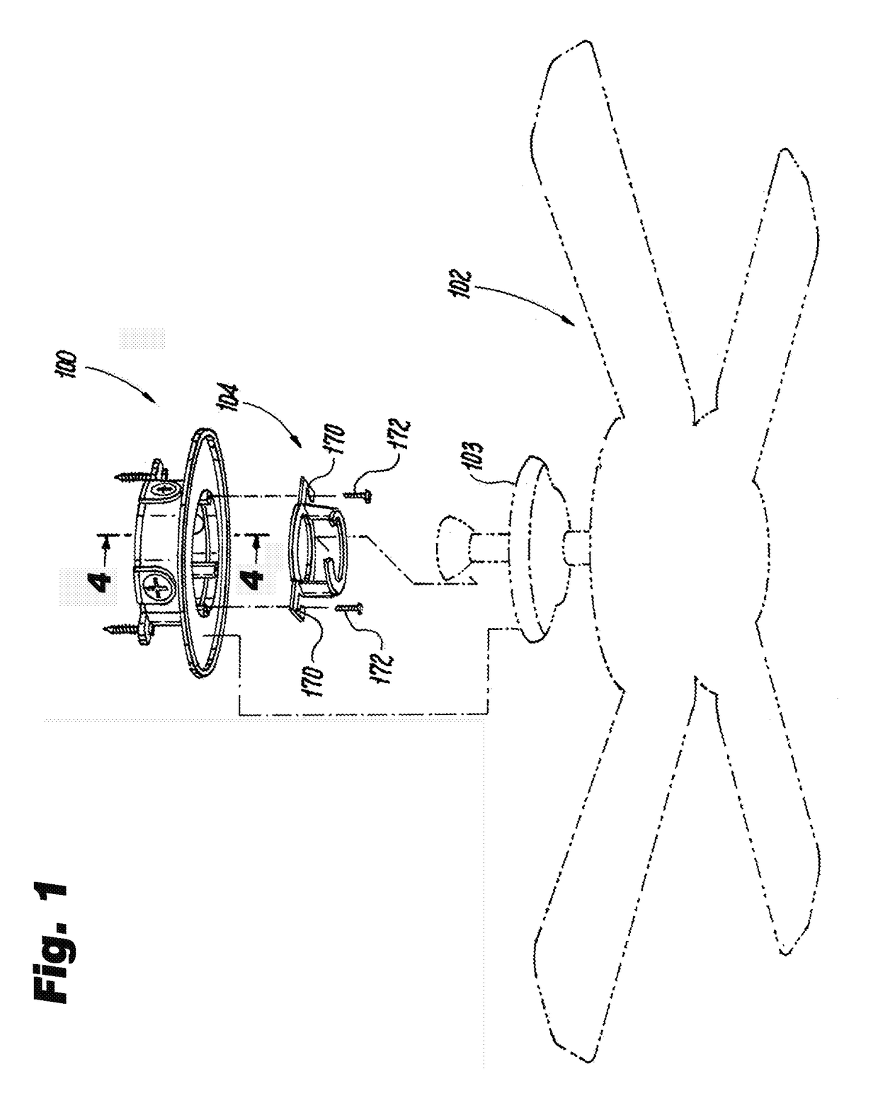
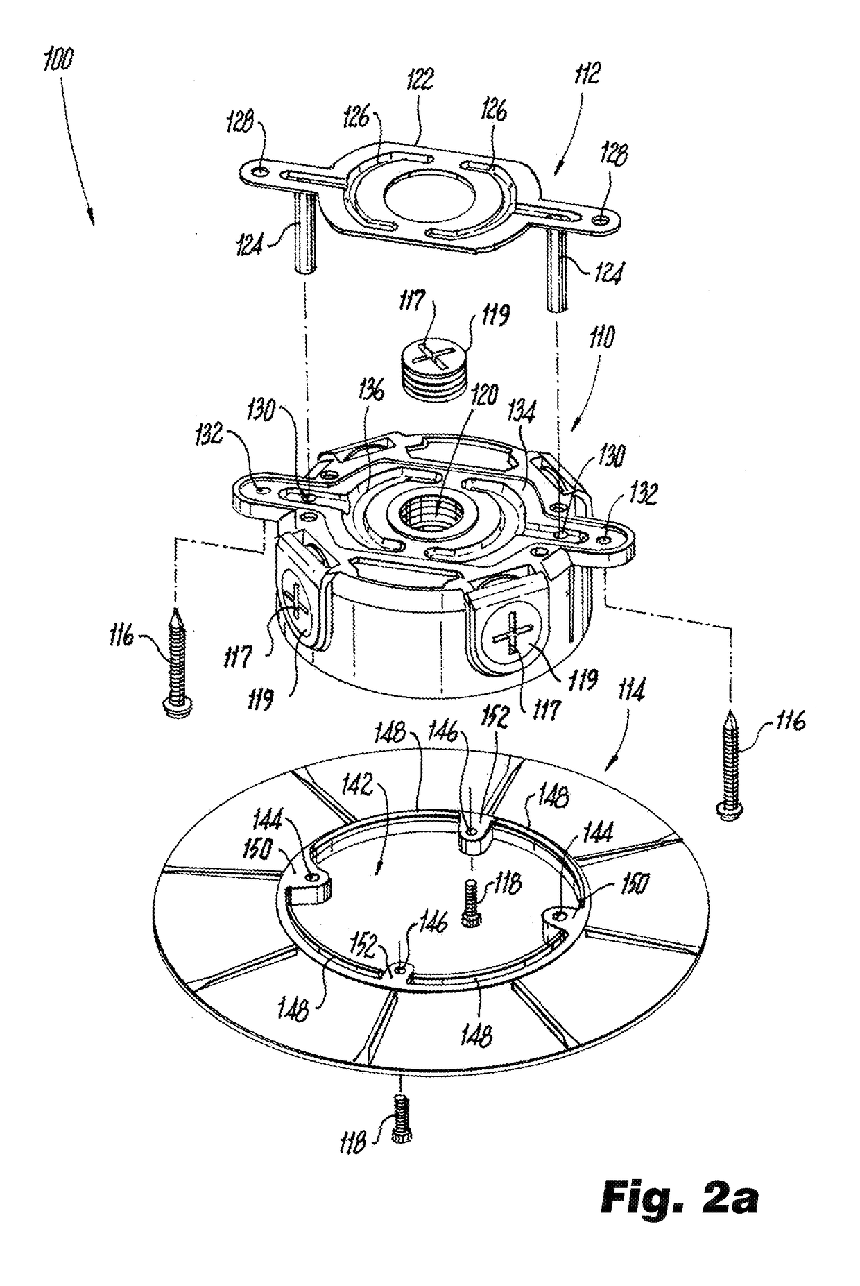
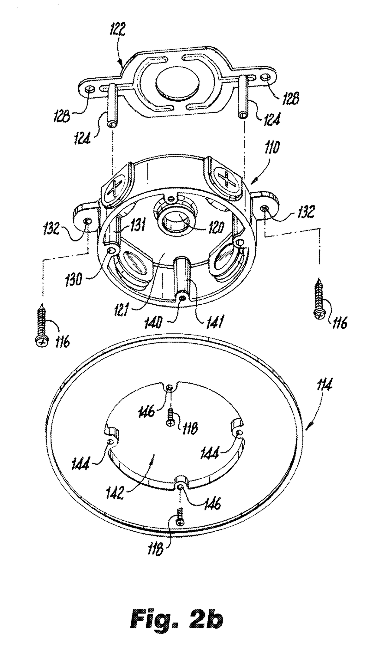
[0032]The present disclosure provides descriptions of embodiments for a weatherproof electrical box assembly having an electrical box and a reinforcement member for supporting and facilitating electrical connections to ceiling mounted electrical fixtures. The electrical box assemblies according to the present disclosure may be referred to herein as the “box assembly” in the singular and the “box assemblies” in the plural. The electrical box may be referred to as the “box” in the singular and the “boxes” in the plural. The electrical fixtures contemplated by the present disclosure include ceiling fans, chandeliers and other electrical fixtures that are heavy and / or require additional structural strength to support the electrical fixture when installed. The electrical fixtures may be referred to herein as the “fixture” in the singular and as the “fixtures” in the plural. This specification and the accompanying drawings are to be regarded in an illustrative sense rather than a restrict...


PUM


Abstract

The present disclosure provides descriptions of electrical box assemblies for supporting heavy fixtures, such as ceiling fans, and facilitating electrical connections to the fixtures. The electrical box assembly includes an electrical box that allows a connection between the box and electrical conduits and a connection, e.g., a weatherproof connection, with a housing of the fixture. The box has an open front face to house electrical connections between the fixture and wires supplying electrical power to the box via the conduits. The box has a bottom wall and an open front face. A reinforcement member fits within the electrical box and includes a panel shaped to conform to at least a portion of the bottom wall and one or more standoffs extending toward the open front face of the box. When the reinforcement member is positioned within the box, mounting holes in the bottom wall of the box and reinforcement member are aligned to allow the box to be attached to a building structure.

Description

CROSS-REFERENCE TO RELATED APPLICATIONS[0001]The present disclosure is based on and claims benefit from co-pending U.S. Provisional Application Ser. No. 62 / 528,659 filed Jul. 5, 2017 entitled “Weatherproof Electrical Enclosure with Reinforcement” and from co-pending U.S. Provisional Application Ser. No. 62 / 646,089 filed Mar. 21, 2018 entitled “Weatherproof Electrical Enclosure with Reinforcement” the contents of both applications are incorporated herein in their entirety by reference.BACKGROUNDField[0002]The present disclosure relates generally to electrical boxes. More particularly the present disclosure relates to electrical boxes made of non-conductive materials and a reinforcement member to support ceiling fans and other heavy fixtures.Description of the Related Art[0003]Connection of ceiling-mounted electrical fixtures, such as ceiling fans, chandeliers and the like, is typically accomplished by installing an electrical box to a structural member within the ceiling, connecting ...

Claims


Application Information

Patent Timeline
IPC IPC(8): H02G3/08H02G3/10H02G3/06F04D25/08
CPCH02G3/083F04D25/088H02G3/0616H02G3/10H02G3/086H02G3/20F04D29/601
Inventor THOMAS, JASON PETER
Owner HUBBELL INC
Why Eureka
Try Eureka