Locking device for spindle of electric tool

Inactive Publication Date: 2019-01-17
BEST SELECT IND SUZHOU CO LTD
View PDF14 Cites 7 Cited by
  • Summary
  • Abstract
  • Description
  • Claims
  • Application Information

AI Technical Summary

Benefits of technology

[0022]According to the locking device for the spindle of the electric tool, when the power output disc is active, the sectorial convex parts of the power output disc abut against the planes of the multi-surface shaft to drive the output shaft to rotate so as to output torque, meanwhile, the convex columns of the power output disc are matched with the insertion grooves in an inserted mode so as to drive the retainer to rotate, the retainer and the output shaft rotate synchronously, and the bearing roller pins serve as bearings; when the power output disc stops output

Problems solved by technology

On this basis, for solving the above problems, it is necessary to provide a locking device for a s

Method used


Image

  • Locking device for spindle of electric tool
  • Locking device for spindle of electric tool
  • Locking device for spindle of electric tool

Examples


Embodiment Construction

[0031]For understanding the invention conveniently, a more comprehensive description of the invention is given with relevant accompanying drawings as follows. Preferred embodiments of the invention are given in the drawings. However, the invention can be realized in various different forms and is not limited to the embodiments in the description. On the contrary, the embodiments are provided for a more thorough and comprehensive understanding of the content disclosed by the invention.

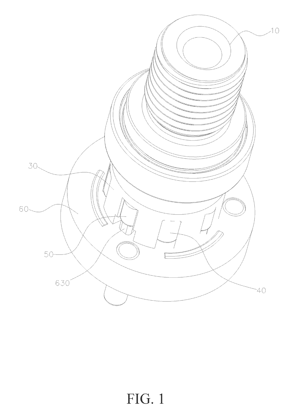
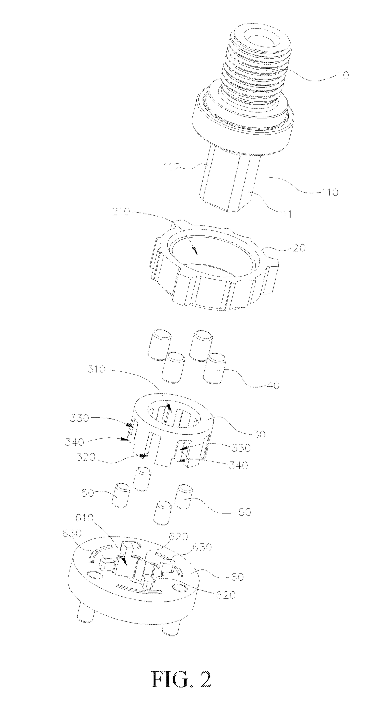
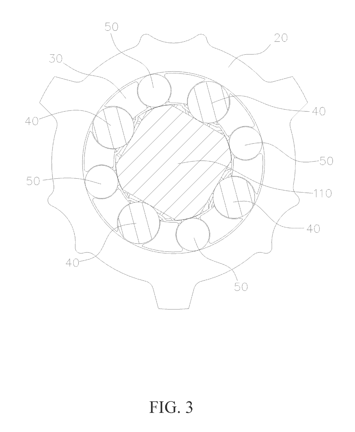
[0032]As is shown in FIGS. 1-6, a locking device for a spindle of an electric tool comprises:

[0033]an output shaft 10, wherein the output shaft is provided with a multi-surface shaft 110 with the outer-diameter portion being polygonal on the whole, every two adjacent planes 111 of the multi-surface shaft 110 are connected through arc surfaces 112 of the same circumference, and the arc surfaces 112 are concentric with the output shaft 10; the output shaft 10 is formed on the spindle of the electric tool ...


PUM

PropertyMeasurementUnit
Angleaaaaaaaaaa
Angleaaaaaaaaaa
Angleaaaaaaaaaa

Abstract

A locking device for a spindle of an electric tool comprises an output shaft, a fixing ring, a retainer, locking roller pins, bearing roller pins and a power output disc. When the power output disc is active, the power output disc drives the output shaft to rotate thus outputting torque and meanwhile driving the retainer to rotate synchronously; when the output shaft is active, the output shaft rotates to make the planes of the multi-surface shaft of the output shaft deflect and drives the locking roller pins to abut against the fixing ring so as to lock the spindle. In the locking process, under the supporting effect of the bearing roller pins, the spindle rotates in a balanced mode and is stressed uniformly, the locking reliability is high, and the overall structure assembling difficulty is low.

Description

BACKGROUND OF THE INVENTIONTechnical Field[0001]The invention relates to the technical field of electric tools, in particular to a locking device for a spindle of an electric tool.Description of Related Art[0002]Electric tools are generally driven by electric power and include plugging-in electric tools, charging electric tools, charging and plugging-in dual-use electric tools and the like, the electric tools can clamp drill bits for drilling or clamp screwdrivers for mounting and dismounting screws. The charging electric tools can fail to drive the drill bits or the screwdrivers to rotate due to insufficient electric power and cannot be charged instantly for use; the plugging-in drill bits cannot be used when sudden power failures occur, and thus electric tools need to serve as manual drills.[0003]According to the structure of the electric tool, a motor driving shaft is driven to rotate by combining a driving gear with the motor driving shaft to be directly engaged with a gear set ...

Claims


Application Information

Patent Timeline
IPC IPC(8): B25F5/00B25F5/02
CPCB25F5/001B23B45/02B25B21/00B25F5/02
Inventor WANG, QIANGJEN, HSI-JENCHIU, YI-TUNG
Owner BEST SELECT IND SUZHOU CO LTD
Why Eureka
Try Eureka