Valve grinding tool

Active Publication Date: 2019-01-31
JEFFRO INC
View PDF7 Cites 3 Cited by
  • Summary
  • Abstract
  • Description
  • Claims
  • Application Information

AI Technical Summary

Benefits of technology

This patent describes a valve assembly that includes a spring cup which is attached to the end of an outer adjustment sleeve. The spring cup holds a part of the valve assembly and fits tightly to ensure that there is no play between them. This helps in achieving smooth grinding of the valve stem during assembly.

Problems solved by technology

After resurfacing valve seats, the distance from the valve seat to the opposite side of the cylinder head may have decreased, which affects valve lash.
This clearance must be tightly controlled—too little and the valves may not seat properly, too much creates valve train noise and excess load on the valves and valve train components.
Maintaining an inventory of shims is impractical for many machinists.
Ordering consumes time, which, means delayed job completion and delayed payment.

Method used


Image

  • Valve grinding tool
  • Valve grinding tool
  • Valve grinding tool

Examples


Embodiment Construction

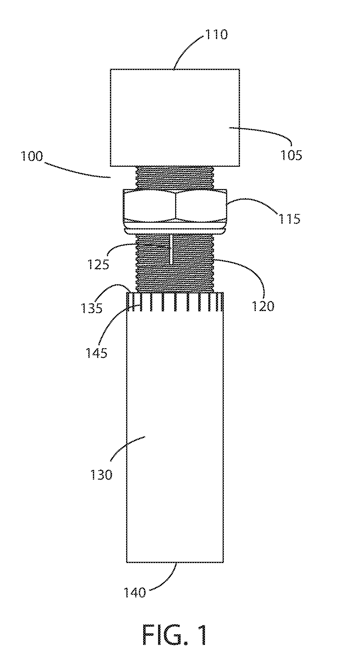
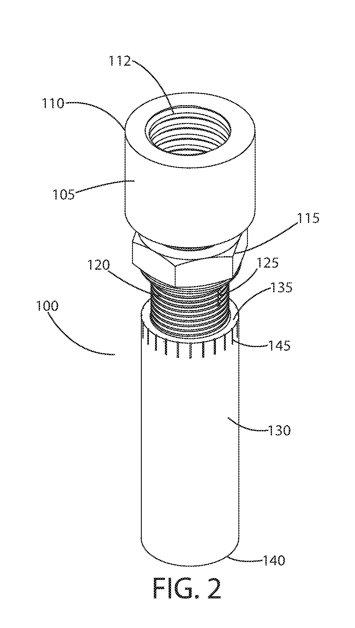
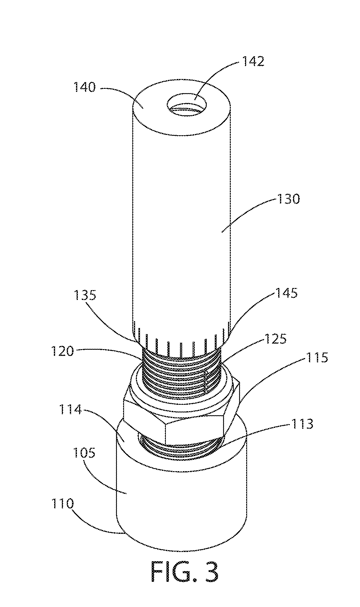
[0047]With reference to FIGS. 1 through 6, an exemplary valve grinding tool 100 according to principles of the invention includes a coupling 105, an inner adjustment sleeve 120, a lock nut 115, and an outer adjustment sleeve 130. The coupling 105 is a sleeve (i.e., a structure with a central cylindrical channel 112 extending from end 110 to end 114). One end 110 of the coupling 105 receives and threadedly engages a threaded nose 410 of a rotary tool 400 (FIG. 12). The opposite end 114 of the coupling 105 receives and threadedly engages an end 113 of the inner adjustment sleeve 120. Thus, the function of the coupling 105 is to couple a rotary tool 400 to the inner adjustment sleeve 120.

[0048]The inner adjustment sleeve 120 of the exemplary tool 100 is a sleeve with external threads. A central channel 155 extends through the sleeve 120. The inner surface of the channel 155 may be smooth or threaded, as shown in FIGS. 5 and 6. However, inner threads are not necessary unless another com...


PUM


Abstract

A tool includes a coupling, an inner adjustment sleeve, and an outer adjustment sleeve. The coupling connects a rotary tool to the inner adjustment sleeve. An adjustable portion of the inner adjustment sleeve is threadedly received in the outer adjustment sleeve. An offset aperture in the free end of the outer adjustment sleeve receives a tip of a valve stem for grinding. An optional cup at the end of the outer adjustment sleeve stabilizes the tool. A grinding bit with a shaft retained in a collet of the rotary tool is contained internally, in a channel, extending through the tool.

Description

RELATED APPLICATION[0001]This application is a nonprovisional and claims the benefit of priority of U.S. Provisional Patent Application No. 62 / 536,941, filed Jul. 25, 2017, the entire contents of which are incorporated herein and made a part hereof.FIELD OF THE INVENTION[0002]This invention relates generally to internal combustion engines, and, more particularly, to a tool for grinding tips of poppet valves for appropriate clearance.BACKGROUND[0003]During a typical valve job, valve seats of the cylinder heads are resurfaced. Some cylinder heads have integral valve seats, while others have replaceable hardened steel valve seats. Replaceable valve seats can be removed and replaced. Integral seats are typically milled to allow the insert of a new seat. After resurfacing valve seats, the distance from the valve seat to the opposite side of the cylinder head may have decreased, which affects valve lash.[0004]Valve lash or valve clearance is the gap between the rocker arms or bucket follo...

Claims


Application Information

Patent Timeline
IPC IPC(8): B24B41/06B24B7/16
CPCB24B41/067B24B7/16B24B23/02
Inventor BRIGHT, JEFFERY W.MCGRIFF, ROY
Owner JEFFRO INC
Why Eureka
Try Eureka