Method for compacting soil, applications of this method and devices for its implementation

a soil compacting and soil technology, applied in soil preservation, railway tracks, roads, etc., can solve the problems of surface lamination detrimental to the long-term behavior/performance of the structure, the density obtained by compaction is not uniform throughout the thickness of the layer, and the stress induced within the material decreases

Active Publication Date: 2011-09-29
MEDINGER R&D
View PDF57 Cites 2 Cited by
  • Summary
  • Abstract
  • Description
  • Claims
  • Application Information

AI Technical Summary

Benefits of technology

[0013]To solve these problems, the invention provides a method and devices that allow to com

Problems solved by technology

The stresses induced within the material decrease as the depth increases and consequently the density obtained by compaction is not uniform throughout the thickness of the layer.
Therefore, for silt or clay like soils treated with an hydraulic binder (in particular silts, more or less clayey fine sands), the maximum thickness of the compacted layer is in practice limited to 30 or 35 centimeters, because the use of the heaviest vibrating equipments would cause a surface lamination detrimental to the long term behavior/performance of the structure.
Moreover, the difficulties relating to the

Method used


Image

  • Method for compacting soil, applications of this method and devices for its implementation
  • Method for compacting soil, applications of this method and devices for its implementation
  • Method for compacting soil, applications of this method and devices for its implementation

Examples


first embodiment

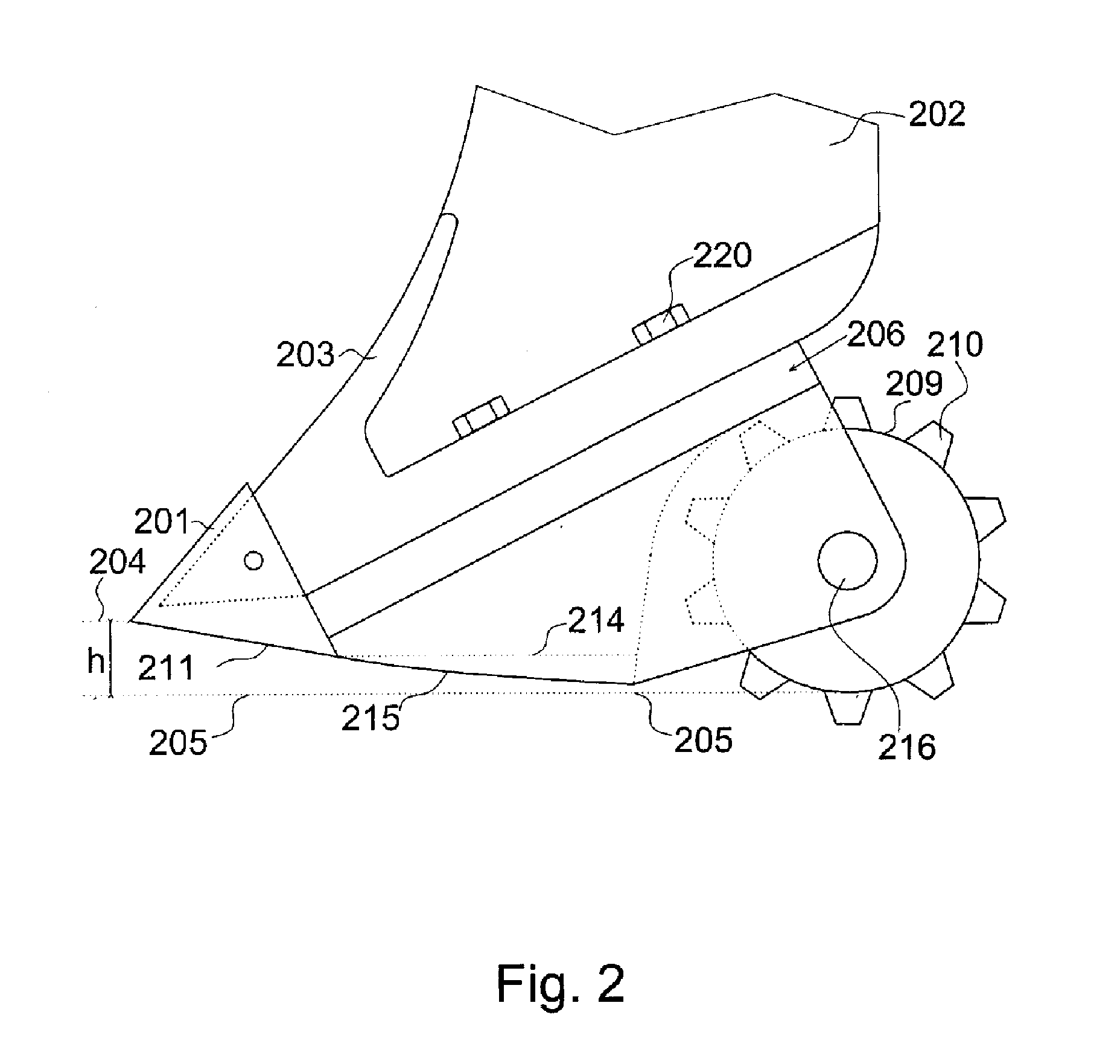
[0066]In the embodiment of FIG. 2, there is a wedge 201, similar to the wedge 101, attached to a vertical post or to a rotor branch 202 by means of an intermediate part 203 which serves as a base for all the tools. The upper layer, again not shown in the Figure, is separated by the wedge 201 from the virtual surface 204 and is subjected to the same treatment as in the previous example. However, in this case, the wedge 201 is tilted downward so that its lower face 211 comes to press the surface 204 to achieve a first compaction that generates a real surface 214. Part 206, attached by bolts 220 to the plate of the base 203, is formed at the front by a short length base plate 215 and at the rear by a large cylinder which can be smooth or toothed, or be provided with sheep's foot rollers 210. This cylinder is tangent to the extension of the profile of the base plate. The cylinder rotates freely about an axis 216 retained by the sides of the part 206. In contact with the soil, the cylind...

third embodiment

[0067]In a third embodiment, shown in FIGS. 3 and 4, the stripping member is reduced to a simple wear plate 301 particularly resistant, for example in tungsten carbide, attached to an intermediate part 303 by welding or possibly by removable means. This intermediate part acts, as above, as a common support to the blade 301 and to the members described below. The upper layer of the soil, not shown, is treated as in the two previous embodiments. The compaction of the virtual surface 304, allowing to bring this surface 304 back at the desired level of the surface 305 by a compacting of a height h, is obtained in this embodiment by a set of small rollers 309 of small diameter. These rollers are arranged substantially next to each other, parallel to the surface of the soil and perpendicular to the direction of motion of the device. They are attached to another intermediate part 313 which has in this embodiment, downwardly, substantially a U shape with two vertical wings on the sides and ...

fourth embodiment

[0068]FIG. 5 shows known members which can be used in a

[0069]These members include an intermediate part 503 which can be mounted on any support, such as for example a branch of a star 522, through a transverse hole 502 and a bolt not shown. It also includes a longitudinal hole, not visible in the Figure, to receive soil milling tools, such as a pick 511 or a tooth 501 / 531, which are maintained by a key 504. It is to be noted that the pick 511 and the tooth 531 are particularly reinforced as compared to the standard tooth 501.

[0070]A fourth embodiment, shown according to a first example in FIG. 6, comprises an intermediate part as described above, completed by a flat part 513 attached, for example by welding, on the lower end of the part 503 to obtain an intermediate part within the meaning of the invention.

[0071]This intermediate part is fixed by its hole 502 to a vertical post 522 of a frame, or to the end of a branch of a star. It is provided for example with a pick 511 or a tooth...


PUM


Abstract

The invention relates to the methods allowing to compact the soil, and devices for carrying out these methods.
It comprises the insertion into the soil at a predetermined depth (h) under which the compaction by the upper level of the soil becomes ineffective, of an underground compacting device. By advancing this device, the soil (104) can be compacted below this specified depth.
Thanks to this invention it is possible to compact thicker layers and to improve the railway tracks repairing systems.

Description

CROSS REFERENCE TO RELATED APPLICATIONS[0001]Applicant claims priority under 35 U.S.C. 119 of French patent application no. 1001152 filed on 23 Mar. 2010.BACKGROUND OF THE INVENTION[0002]The present invention relates to methods for compacting soils. It aims at increasing the density of the materials in depth, so as to improve the geotechnical characteristics of the considered layer. It concerns new construction works such as construction of foundation layers for road structures, airport structures, railway structures, etc., as well as the maintenance and repair works performed under a railway, without having to proceed to the removal of the rails and of the ties.[0003]It is known that compaction of soils or granular materials spread into a layer is usually carried out by means of compactors moving on the upper part of the layer. The compactors thus apply to the upper part of the layer an effort that will induce a pressure within the material and cause the irreversible deformations o...

Claims


Application Information

Patent Timeline
IPC IPC(8): E02D3/02E02D3/026E02D3/054
CPCE01B27/00E01C21/00E02F9/2816E02F5/027E02F5/103E02D3/026
Inventor MEDINGER, JEAN-CLAUDE
Owner MEDINGER R&D
Why Eureka
Try Eureka