Propeller control system for an aircraft

a control system and propeller technology, applied in the direction of propellers, aircraft components, transportation and packaging, etc., can solve the problems of primary control valve failure or unresponsiveness, propeller assembly can experience an overspeed condition, propeller assembly can experience an underspeed condition,

Pending Publication Date: 2019-01-31
GE AVIATION SYST LTD +2
View PDF3 Cites 14 Cited by
  • Summary
  • Abstract
  • Description
  • Claims
  • Application Information

AI Technical Summary

Benefits of technology

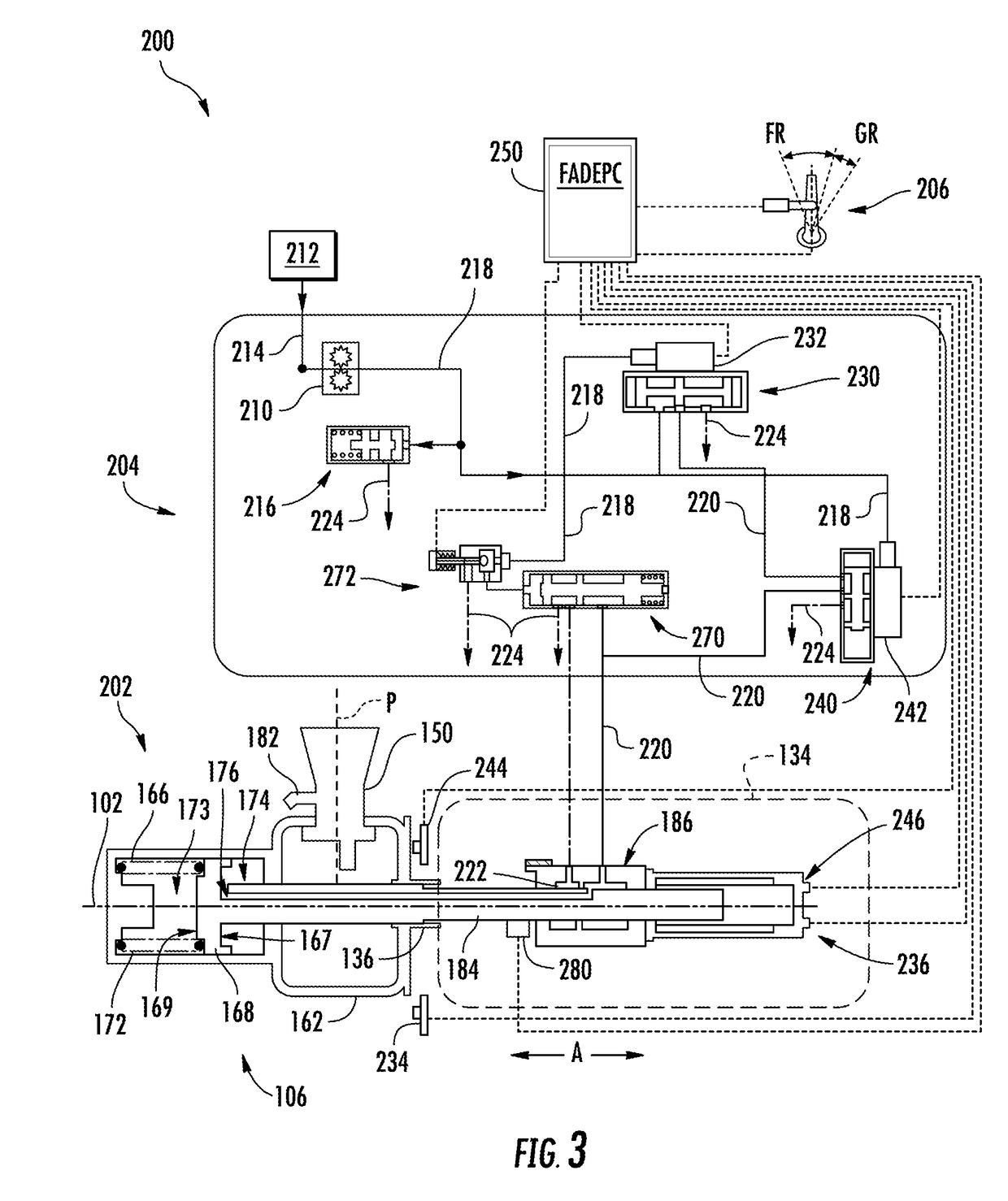
[0008]In one exemplary aspect, the present subject matter is directed to an engine defining an axial direction, a radial direction, and a circumferential direction. The engine includes a variable pitch propeller assembly driven by the engine. The propeller includes a plurality of propeller blades rotatable about the axial direction and spaced apart along the circumferential direction, each propeller blade rotatable through a plurality of blade angles about their respective pitch axes each extending in the radial direction. The engine further including a propeller control system that includes a pitch actuation assembly for adjusting the plurality of propeller blades through the plurality of blade angles. The propeller control system also includes a pitch control unit. The pitch control unit includes a primary control valve configured to selectively allow a flow of hydraulic fluid to or from the pitch actuation assembly. The pitch control unit also includes a protective control valve configured to selectively allow a flow of hydraulic fluid to or from the pitch actuation assembly. The pitch control unit further includes a controller communicatively coupled with the primary control valve and the protective control valve, wherein the controller is configured to: determine a condition of the engine; and to control the protective control valve to selectively allow a controlled amount of hydraulic fluid to or from the pitch actuation assembly based at least in part on the condition of the engine.

Problems solved by technology

In some instances, the propeller assembly can experience an overspeed condition, which occurs when propeller RPM increases above the reference speed, and in some instances, the propeller assembly can experience an underspeed condition, which occurs when propeller RPM decreases below the reference speed.
In some cases, however, the primary control valve can fail or can be unresponsive when the propeller assembly experiences an overspeed condition.
However, such conventional mechanical overspeed governors include many parts, increase the weight of the engine, and typically include overspeed testing components (e.g., solenoid test valves) for ensuring proper operation of the overspeed governor.
The weight of the overspeed governor and overspeed testing components are penalties on the efficiency of the engine.
This penalty is costly as the overspeed governor and testing components are used relatively infrequently.
Such conventional solenoid-operated feather valves and accompanying sensing components can increase the weight of the engine, which is a penalty on the efficiency of the engine.
This penalty is costly as the feather valve is used relatively infrequently.

Method used


Image

  • Propeller control system for an aircraft
  • Propeller control system for an aircraft
  • Propeller control system for an aircraft

Examples


Embodiment Construction

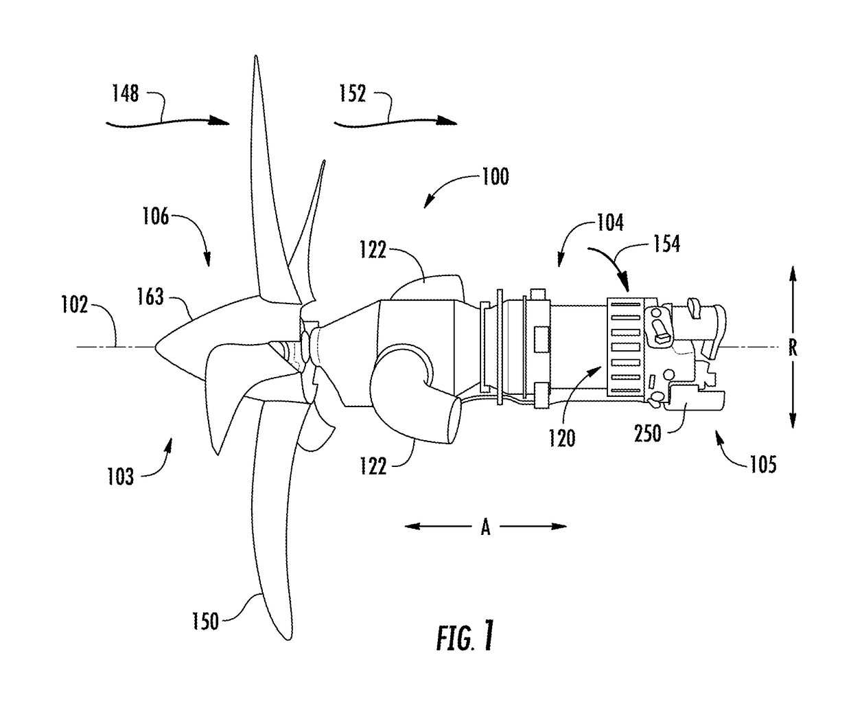
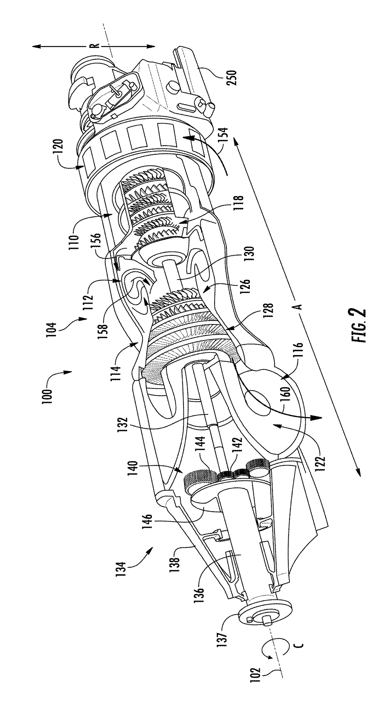
[0035]Reference now will be made in detail to embodiments of the invention, one or more examples of which are illustrated in the drawings. Each example is provided by way of explanation of the invention, not limitation of the invention. In fact, it will be apparent to those skilled in the art that various modifications and variations can be made in the present invention without departing from the scope or spirit of the invention. For instance, features illustrated or described as part of one embodiment can be used with another embodiment to yield a still further embodiment. Thus, it is intended that the present invention covers such modifications and variations as come within the scope of the appended claims and their equivalents.

[0036]As used herein, the terms “first”, “second”, and “third” may be used interchangeably to distinguish one component from another and are not intended to signify location or importance of the individual components. The terms “upstream” and “downstream” r...


PUM


Abstract

Propeller control systems and methods for controlling the pitch of a plurality of propeller blades of a variable pitch propeller assembly operatively coupled with an engine is provided. In one exemplary aspect, the propeller control system includes features for combining overspeed and feathering protective functions in a protective control valve communicatively coupled with a controller. In such an event the controller controls the protective control valve to selectively allow a controlled amount of hydraulic fluid to flow to or from a pitch actuation assembly such that the pitch of the propeller blades can be adjusted based at least in part on the condition of the engine.

Description

FIELD[0001]The present subject matter is generally related to variable pitch propeller assemblies and more particularly to control systems for variable pitch propeller assemblies.BACKGROUND[0002]Variable pitch propeller assemblies for aircraft are operatively configured to adjust propeller blades of the propeller assembly through a plurality of blade angles. In this manner, the propeller blades can be adjusted to a propeller blade angle that optimizes engine performance for given flight conditions. To adjust the propeller blade angle of the propeller blades, variable pitch propeller assemblies typically include a pitch control unit. Certain pitch control units can include a primary pitch control valve or governor controlled by an electrohydraulic servovalve (EHSV). Based on one or more input signals, the primary control valve selectively allows an amount of hydraulic fluid to flow to or drain from a pitch actuation assembly positioned within the propeller assembly. By altering the a...

Claims


Application Information

Patent Timeline
Patent Type & Authority Applications(United States)
IPC IPC(8): B64C11/40B64C11/30B64C11/44B64C11/38
CPCB64C11/40B64C11/303B64C11/44B64C11/385B64C11/30
Inventor CALKINS, STEVEN CLARKCARRINGTON, CHRISTOPHER ROYKENNEY, THOMAS BRADLEYCASTELLANI, SIMONEFLETCHER, JR., ALBION RICHARDSON
Owner GE AVIATION SYST LTD
Why Eureka
Try Eureka