Spotlight apparatus and manufacturing method thereof

Active Publication Date: 2019-02-21
LEEDARSON AMERICA INC
8 Cites 2 Cited by

AI-Extracted Technical Summary

Problems solved by technology

However, spotlight devices usually takes higher price and thus making them less adopted than needed.
Current spotlight devices usually have more complicated structures and thus make them having higher c...

Method used

[0053]In another specific example, there are diffusion optical structures formed on the dorm portion and the tube portion, e.g. to increase overall light output and to prevent visual exposing of the components of the spotlight apparatus.
[0054]In another specific example, the two metal pins have openings respectively for receiving the two input terminals of the driver plate. In other words, the two input terminals may not need to be welded but just plugged into the metal pins. This helps significant decrease manufacturing cost.
[0056]In another specific example, a portion of the input terminals of the driver plate is deformed when the input terminals are inserted into the openings of the two metal pins to keep better connection between the input terminals and the two metal...

Benefits of technology

[0022]To further increase heat dissipation, heat dissipation gel may be applied between the track trench and the driver plate to enhance heat dissipation.
[0023]Alternatively, heat...

Abstract

A spotlight apparatus has a LED plate, a lens plate, a cup body, a driver plate and two metal pins. The lens plate has a central lens and a plurality of micro optical structures. The cup body has a dome portion, a tube portion and a bottom portion. The dome portion and the tube portion are manufactured together as a single body. A portion of light emitting from the LED plate runs through the central lens of the lens plate to form a focus light beam and another portion of light emitting from the LED modules running through the plurality of micro optical structures to form soft light. Two input terminals of the driver plate are inserted into the two metal pins.

Application Domain

Technology Topic

Lead plateEngineering +2

Image

  • Spotlight apparatus and manufacturing method thereof
  • Spotlight apparatus and manufacturing method thereof
  • Spotlight apparatus and manufacturing method thereof

Examples

  • Experimental program(1)

Example

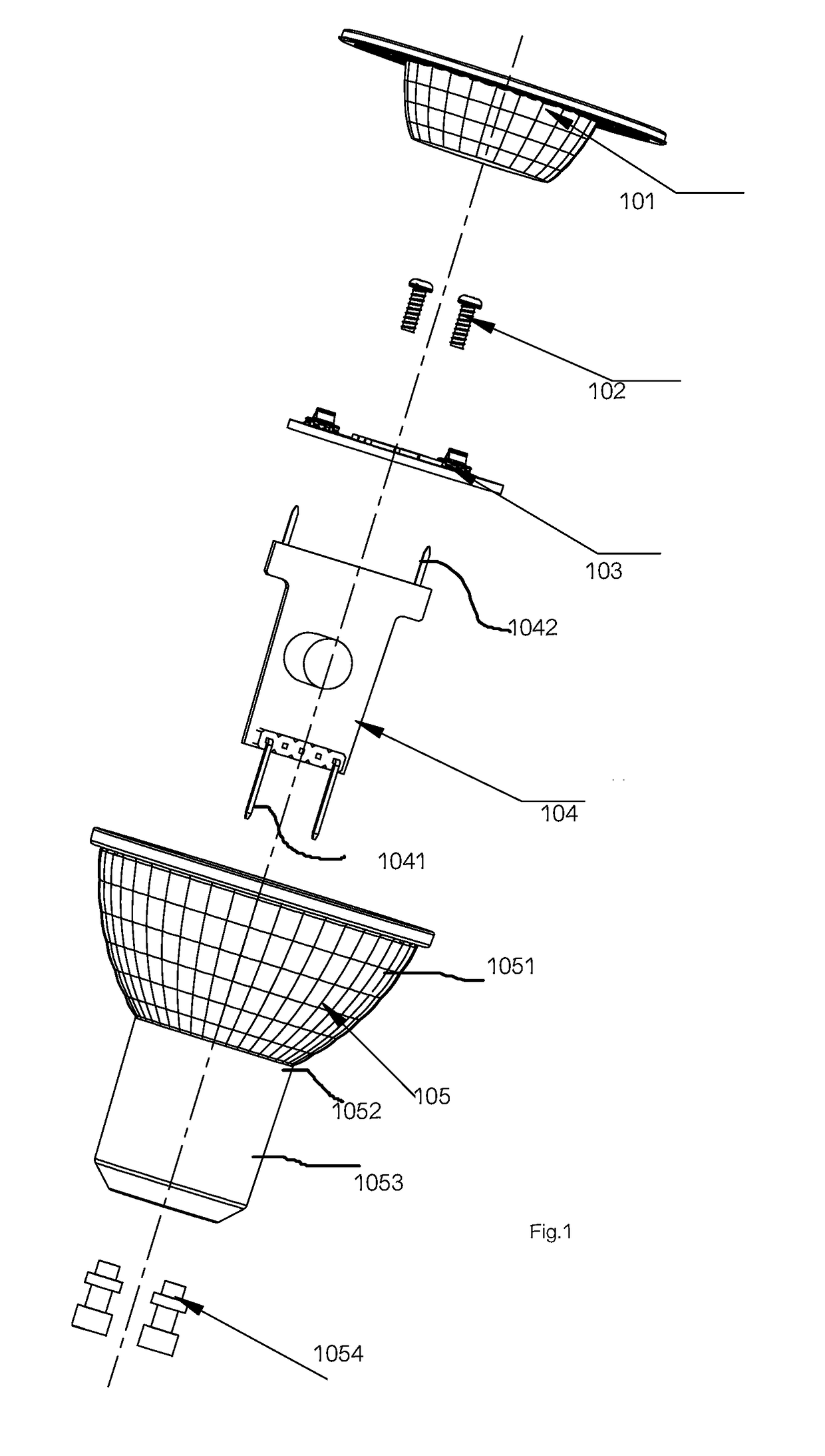
[0042]Please refer to FIG. 1 and FIG. 5. FIG. 1 illustrates an exploded diagram of components of a spotlight apparatus. FIG. 5 illustrates a side view of cross-sectional diagram of the components of FIG. 1 when they are assembled together.
[0043]The spotlight apparatus has a LED plate 103, a lens plate 101, a cup body 105, a driver plate 104, a pair of screws 102 for fixing the components.
[0044]The LED plate 103 has a plurality of LED modules, a metal plate and two connectors. The plurality of LED modules and the two connectors are mounted on the metal plate. The LED modules may each be a single LED chip or multiple LED chips formed as a module.
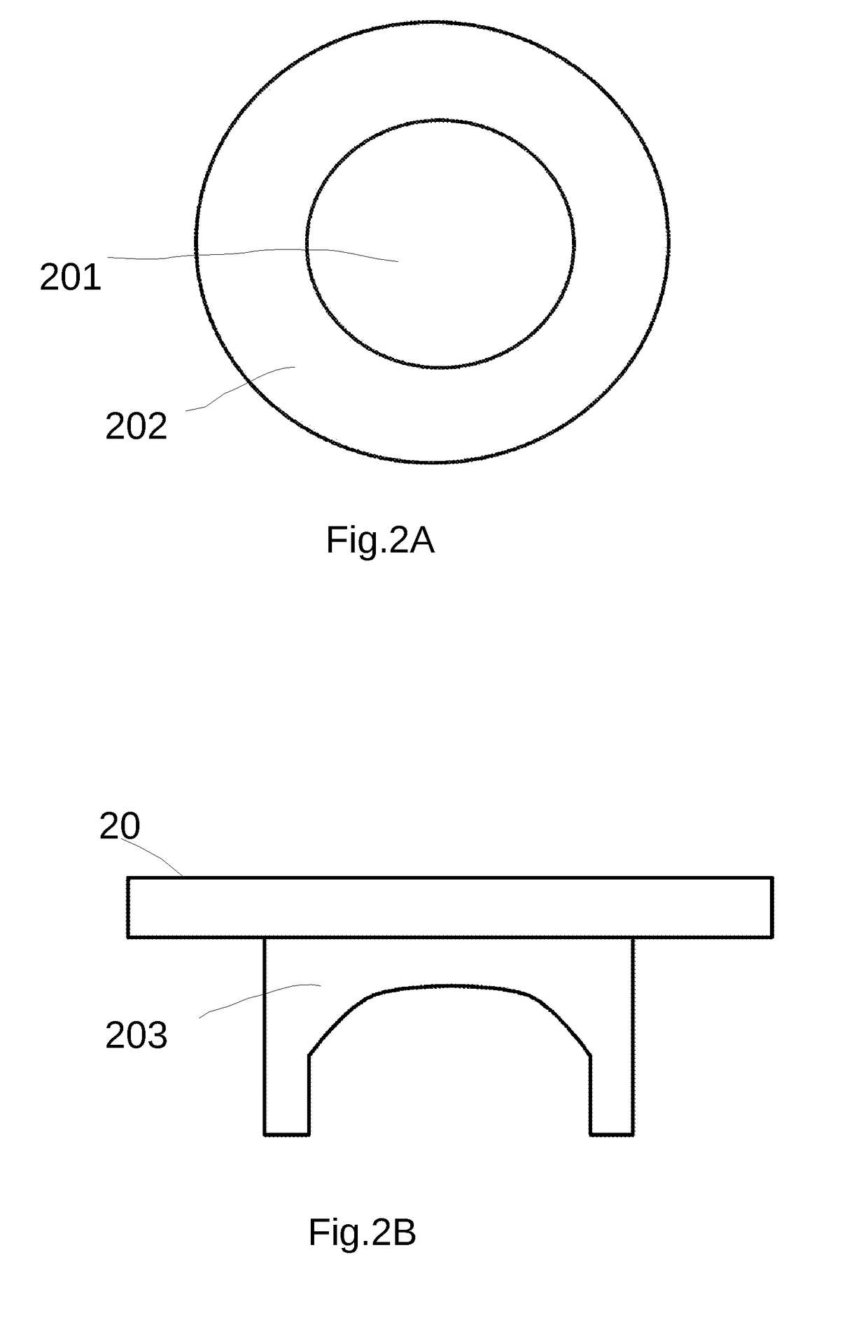
[0045]Please refer to FIG. 2A and FIG. 2B, which illustrate a lens plate example. In FIG. 2A and FIG. 2B, the lens plate is a circular shape and has a central lens 201 and a plurality of micro optical structures 202 around the central lens. Micro optical structures are patterns including concave or other structure that may guide or change light paths to achieve certain optical effect. FIG. 2B is a side view of FIG. 2A. The lens plate 20 has a transparent hollow cup 203 structure for guiding light entering the central lens 201. The central lens 201 may be made of a single lens or multiple lens that generates the effect of creating a spotlight beam.
[0046]Different lens plate may be prepared for generating spotlight apparatuses with different light beam characteristics while the other components kept unchanged.
[0047]Therefore, a detachable connection structure like screw or clips may be designed so that users may change a different lens plate to fit their needs. For example, a user may buy such spotlight apparatus with a number of lens plates with different central lens settings. The user may replace the default lens plate with another lens plate, e.g. to emit a more wide light beam or a narrower light beam. In addition, different colors of lens plate may be designed so that users may change a different color filter to affect the light beam from such spotlight apparatus.
[0048]Please refer back to FIG. 1. The cup body 105 has a dome portion 1051, a tube portion 1053 and a bottom portion, which facing to and integrated with two metal pins 1054. The dome portion 1051 and the tube portion 1053 are manufactured together as a single body. The lens plate 101 is fixed to a top peripheral end of the dome portion 1051 of the cup body 105. The LED plate 103 is disposed inside the dorm portion 1051 so that a portion of light emitting from the LED modules running through the central lens of the lens plate 101 to form a focus light beam and another portion of light emitting from the LED modules running through the plurality of micro optical structures to form soft light. The plurality of micro optical structures may be designed to diffuse the light or made of tiny cave, blocks or dots. The central lens may also be made of multiple lens structures instead of a single lens.
[0049]The driver plate 104 contains driver circuits, two output terminals and two input terminals.
[0050]The two metal pins 1054 are integrated to the bottom portion of the cup body 105. The two input terminals 1041 of the driver plate 104 are inserted into the two metal pins 1054 and the two output terminals 1042 connected to the LED plate 103.
[0051]In a specific example, there is a neck portion 1052 between the dorm portion and the tube portion.
[0052]Please also refer to FIG. 3. There is a first distance 302 between where the LED plate 312 is disposed and the neck portion 311. There is a second distance 301 between the top peripheral 313 and the neck portion 311. The first distance 302 is smaller than half of the second distance 301 and larger than one fourth of the second distance 301. For example, the first distance 302 is about ⅓ of the second distance 301. Such arrangement makes both light efficiency and heat dissipation for leaving space for heat movement.
[0053]In another specific example, there are diffusion optical structures formed on the dorm portion and the tube portion, e.g. to increase overall light output and to prevent visual exposing of the components of the spotlight apparatus.
[0054]In another specific example, the two metal pins have openings respectively for receiving the two input terminals of the driver plate. In other words, the two input terminals may not need to be welded but just plugged into the metal pins. This helps significant decrease manufacturing cost.
[0055]In another specific example, the two metal pins are metal hollow tubes. For example, the two metal pins are cylinder shape with central opening.
[0056]In another specific example, a portion of the input terminals of the driver plate is deformed when the input terminals are inserted into the openings of the two metal pins to keep better connection between the input terminals and the two metal pins. The input terminal may be made with elastic metal so that when the input terminals are plugged into the metal pins, the input terminals has form changing and increasing force to fix to the metal pins.
[0057]In another specific example, the two metal pins are molded with the bottom portion of the cup body. For example, the metals are not connected to the bottom portion of the cup body by screw structures. Instead, the metal pins are placed in a molding device while molding the bottom portion of the cup body.
[0058]In a specific example, the dome portion, the tube portion and the bottom portion of the cup body are together formed with Polycarbonate (PC) material as a single body. Please note that other plastic or material may be adopted if they allow light to go through.
[0059]Please refer to FIG. 4, which illustrates interaction between an input terminal of a driver plate 401 and a metal pins 402. The front end of the input terminal is inserted into a hole of the metal pins 402. In addition, a deformation of the inserted portion of the input terminal 401 would help fixing better for the input terminal 401 and the metal pins 402. In another specific example, the two metal pins are inserted in a molding device when the molding device is used for produce the cup body so that the two metal pins are molded with the bottom portion of the cup body.
[0060]In a specific example, the lens plate is made of Polycarbonate material as a single body. In other words, the cup body and the lens plate may be made of same PC material thus making the overall cost even lower.
[0061]In a specific example, the tube portion of the cup body has a track trench for guiding and inserting the driver plate. With such design, the driver plate may be reliably fixed to the tube portion of the cup body.
[0062]In a specific example, the driver plate has a base plate with metal material for heat dissipation. For example, the base plate may be made of aluminum.
[0063]To further increase heat dissipation, heat dissipation gel may be applied between the track trench and the driver plate to enhance heat dissipation.
[0064]Alternatively, heat dissipation glue may be applied between the track trench and the driver plate to enhance heat dissipation and connection reliability between the track trench and the driver plate.
[0065]In a specific example, the lens plate has a transparent hollow cup facing the LED modules.
[0066]Please refer to FIG. 6, which is a flowchart illustrating a method for manufacturing a spotlight apparatus that has following steps.
[0067]Two metal pins are placed in a molding device (step 601).
[0068]A cup body is formed with the molding device (step 602). The cup body has a dorm portion, a tube portion and a bottom portion. In addition, the two metal pins are molded with the bottom portion.
[0069]A driver plate is placed in the cup body (step 603) so that two input pins of the driver plate are inserted into the two metal pins.
[0070]A LED plate is mounted on the driver plate (step 604) so that two output terminals of the driver plate are electrically connected to the LED plate.
[0071]A lens plate is placed (step 605) to a top peripheral end of the dome portion of the cup body.
[0072]In a specific example of the method, the cup body is made of Polycarbonate material.
[0073]In a specific example of the method, the tube portion of the cup body has a track trench for guiding and inserting the driver plate.
[0074]In a specific example of the method, the metal pins two metal pins are two metal hollow tubes, and the two input terminals of driver plate are inserted into the two metal hollow tubes.
[0075]In a specific example of the method, the lens plate has a central lens and a plurality of micro optical structures so that a portion of light emitting from the LED plate running through the central lens of the lens plate to form a focus light beam and another portion of light emitting from the LED plate running through the plurality of micro optical structures to form soft light.
[0076]Please be noted that other variations based on the same inventive spirit should be regarded falling within the protection scopes of the present invention. For example, the metal pins mentioned above may be designed as screw with associated screw grooves on the bottom portion of the cup body. Other ways for integrating the metal pins with the bottom portion of the cup body may also be adopted under different design needs.
[0077]The embodiments mentioned above should not be interpreted as limitation for the present invention. Persons of ordinary skilled in the art would be able to create equivalent designs under protection scopes.

PUM

no PUM

Description & Claims & Application Information

We can also present the details of the Description, Claims and Application information to help users get a comprehensive understanding of the technical details of the patent, such as background art, summary of invention, brief description of drawings, description of embodiments, and other original content. On the other hand, users can also determine the specific scope of protection of the technology through the list of claims; as well as understand the changes in the life cycle of the technology with the presentation of the patent timeline. Login to view more.

Similar technology patents

Electrical connector

Owner:FOXCONN (KUNSHAN) COMPUTER CONNECTOR CO LTD +1

Staggered light collectors for concentrator solar panels

InactiveUS20100126554A1Maximize amountIncrease heat dissipationPhotovoltaic supportsSolar heating energyDead bandSolar energy harvesting
Owner:MORGAN SOLAR INC

Heat dissipation device special for induction cooker

InactiveCN105627389AIncrease heat dissipationDomestic stoves or rangesLighting and heating apparatusCookerCopper
Owner:YICHANG RUIYING ELECTROMECHANICAL

Method for composting pure organic fertilizer from straws

InactiveCN108424185AIncrease heat dissipationShorten the decay cycleBio-organic fraction processingExcrement fertilisersChemistryDry soil
Owner:HUBEI XIANGSHANG FOOD

Classification and recommendation of technical efficacy words

  • Enhance heat dissipation
  • Increase heat dissipation

Filter box with resonator and reservoir

InactiveUS20050279319A1Enhance heat dissipationUnnecessary power use be avoidNon-fuel substance addition to fuelExhaust apparatusAutomotive engineeringResonator
Owner:MANN HUMMEL GMBH

Staggered light collectors for concentrator solar panels

InactiveUS20100126554A1Maximize amountIncrease heat dissipationPhotovoltaic supportsSolar heating energyDead bandSolar energy harvesting
Owner:MORGAN SOLAR INC

Method for composting pure organic fertilizer from straws

InactiveCN108424185AIncrease heat dissipationShorten the decay cycleBio-organic fraction processingExcrement fertilisersChemistryDry soil
Owner:HUBEI XIANGSHANG FOOD

Heat dissipation device special for induction cooker

InactiveCN105627389AIncrease heat dissipationDomestic stoves or rangesLighting and heating apparatusCookerCopper
Owner:YICHANG RUIYING ELECTROMECHANICAL
Why Eureka
Try Eureka