
Immersion nozzle replacement method

a technology of immersion nozzle and replacement method, which is applied in the direction of casting apparatus, melt-holding vessels, manufacturing tools, etc., can solve the problems of molten steel leakage, risk of quality deterioration of steel, and space formed occasionally between the joint planes, so as to achieve the effect of minimizing the leakage of molten steel during replacement and high sealing

Active Publication Date: 2019-03-07
KROSAKI HARIMA CORP
View PDF4 Cites 0 Cited by
  • Summary
  • Abstract
  • Description
  • Claims
  • Application Information

AI Technical Summary

Benefits of technology

The present invention provides a method for replacing an immersion nozzle by using a shaped joint sealer. This method prevents the shaped joint sealer from slipping or scraping off when the upper plane of the new immersion nozzle is pressed against the lower plane of the upper refractory, ensuring high sealability during replacement and minimizing leakage of molten steel. The technical effect is improved efficiency and safety during replacement of immersion nozzles.

Problems solved by technology

However, in this replacement method, the upper nozzle and the immersion nozzle are pressure-joined between the refractory joint planes; therefore, a space can be formed occasionally between the joint planes due to the local abrasion during replacement work as well as the thermal expansion during use thereof or the variance of the plane accuracy at the time of production thereof.
If the space is formed, there are risks of quality deterioration of the steel due to suction of an air through this space, and of leakage of the molten steel from the space.
However, in the replacement method of Patent Document 1, the new immersion nozzle was caused to slide under the state that it was pressed to the upper nozzle; and thus, even the shaped joint sealer was arranged on the upper plane of the new immersion nozzle, this shaped joint sealer was scraped off or taken out by the upper nozzle, so that the shaped joint sealer could not be used.
However, with the replacement method of Patent Document 7, a space is formed between the new immersion nozzle and the upper nozzle during replacement, so that there is a problem that the molten steel drops on the upper plane of the new immersion nozzle thereby becoming foreign matters of the joint interface, resulting in decrease of the sealability.

Method used


Image

  • Immersion nozzle replacement method
  • Immersion nozzle replacement method
  • Immersion nozzle replacement method

Examples


first embodiment

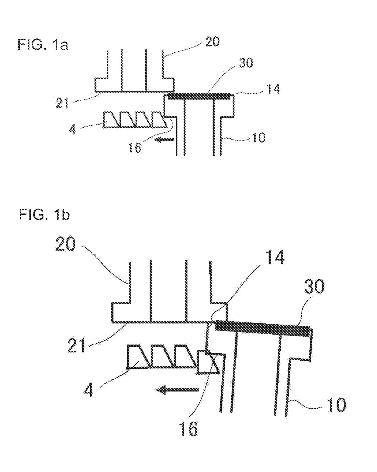
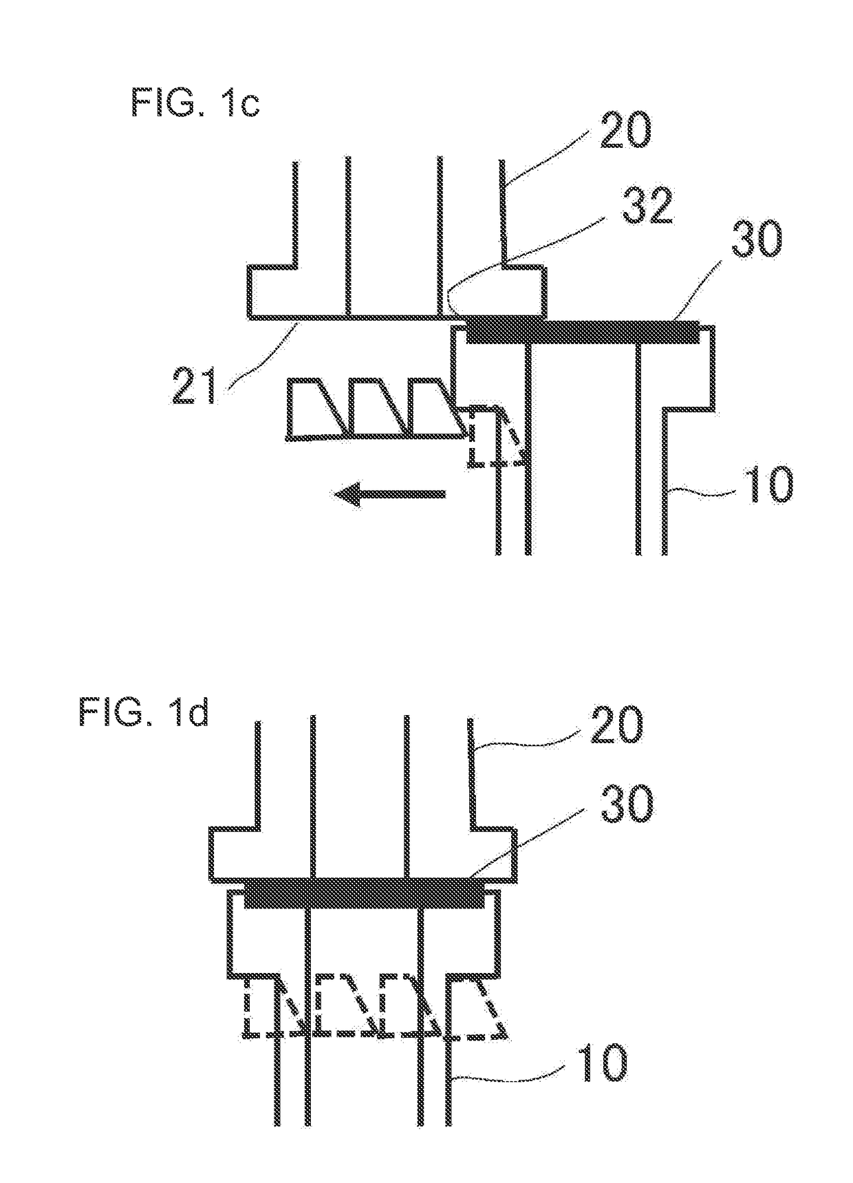
[0057]FIG. 1a to FIG. 1d are the explanatory drawings illustrating an image of the method for replacing the immersion nozzle according to the first embodiment of the present invention.

[0058]In FIG. 1a to FIG. 1d, the new immersion nozzle 10 (hereunder, this is simply called “immersion nozzle 10”) is supported by the keynote boards 4 served as the pressing members that are arranged in parallel in both sides of the flange's lower plane 16 and is caused to slide while being pressed to the upper nozzle's lower plane 21 as the upper refractory. The pressing mechanism by the keynote boards 4 and the sliding mechanism to slide the immersion nozzle 10 are the same as the mechanisms of Patent Document 1 mentioned before (FIG. 10). Specifically, four keynote boards 4 to press the both sides of the flange's lower plane 16 of the immersion nozzle 10 are arranged in one side thereof; and when the immersion nozzle 10 is moved by being pushed to an arrow direction with a driving mechanism not show...

second embodiment

[0071]FIG. 5a is the vertical cross section view of the immersion nozzle used in the second embodiment of the present invention, and FIG. 5b is the top view thereof. In this embodiment, in the immersion nozzle in the first embodiment depicted in FIG. 3a and FIG. 3b, the concave portion 15 of the upper plane thereof is formed so as to open to the immersion nozzle's insertion side plane 17. Specifically, in the concave portion 15 in this embodiment, the length A4 is 165 mm, the width B4 is 140 mm, and the depth is 3 mm. Further, in the shaped joint sealer 30 mounted in the concave portion 15, as depicted in FIG. 6, the length A5 is 160 mm, the width B5 is 130 mm, and the thickness is 3.5 mm, wherein the size thereof is made such that it can be arranged until the immersion nozzle's insertion side plane 17.

[0072]This embodiment is also carried out in a similar manner to that of the first embodiment depicted in FIG. 1a to FIG. 1d. Namely, when the immersion nozzle 10 is moved to the lowe...

third embodiment

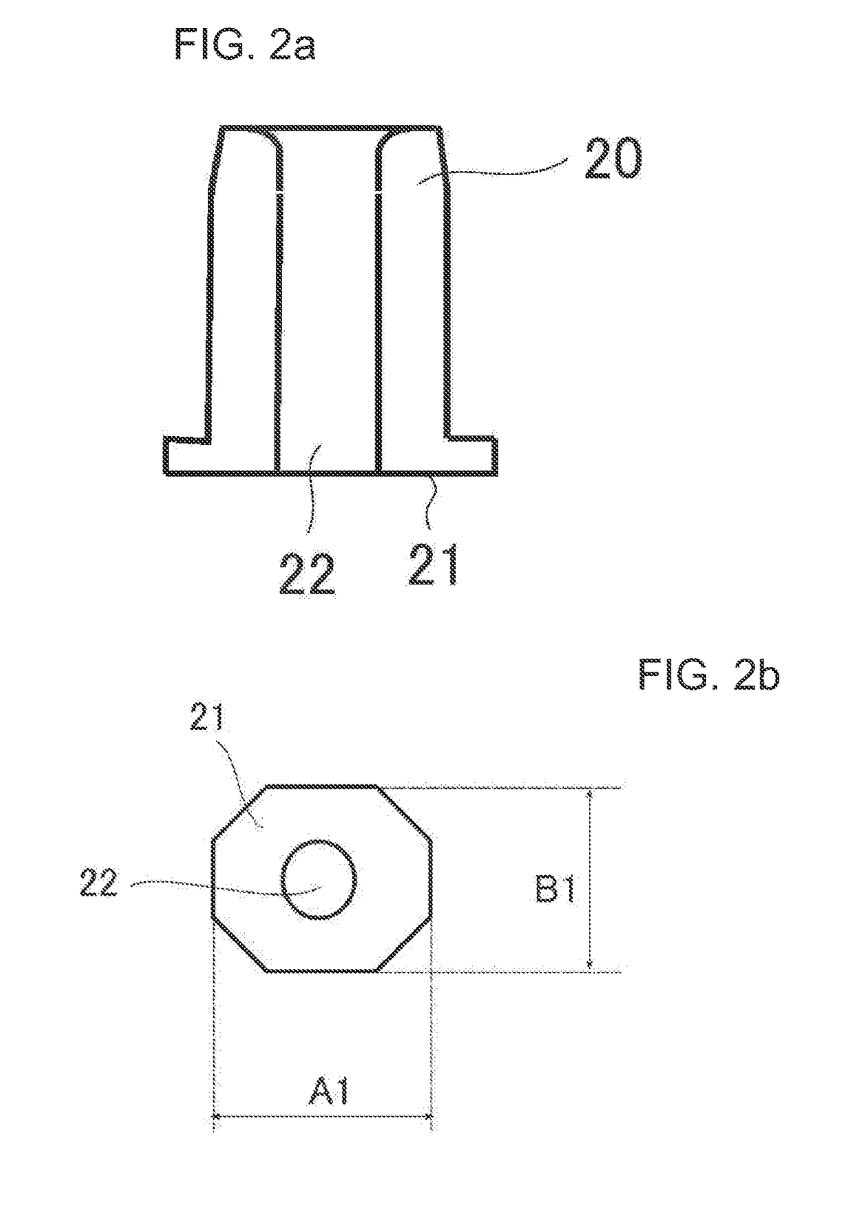
[0074]FIG. 7a is the vertical cross section view of the upper nozzle used in the third embodiment of the present invention, and FIG. 7b is the bottom view thereof. In this embodiment, in the upper nozzle of the first embodiment depicted in FIG. 2a and FIG. 2b, the inclined plane 23 with R 30 mm is made in the lower edge portion thereof in the insertion side of the immersion nozzle. By making the inclined plane 23 like this, not only the slipping of the shaped joint sealer 30 during replacement of the immersion nozzle can be suppressed more surely, but also the smooth joint interface not having irregularity can be formed.

[0075]In the inclined plane that is made in the lower edge portion of the upper nozzle in the insertion side of the immersion nozzle, the shape of the vertical cross section view thereof may be linear or curved. The inclination angle of the inclined plane is preferably in the range of 10 to 70 degrees as the angle formed between the inclined plane and the extended pl...


PUM

PropertyMeasurementUnit
pressing forceaaaaaaaaaa
diameteraaaaaaaaaa
diameteraaaaaaaaaa

Abstract

In the method for replacing an immersion nozzle while pushing out a used immersion nozzle by a new immersion nozzle, in order to minimize leakage of molten steel during the replacement, to enable the use of a shaped joint sealer in a joint interface, and to ensure high sealability, a concave portion is formed on the new immersion nozzle's upper plane so as to include a nozzle hole, and the shaped joint sealer is mounted in this concave portion. The immersion nozzle's upper plane is caused to slide while being pressed to the upper nozzle's lower plane.

Description

TECHNICAL FIELD[0001]The present invention relates to a method for replacing an immersion nozzle used for continuous steel casting.BACKGROUND ART[0002]In continuous steel casting, in order to discharge molten steel from a tundish into a mold, an immersion nozzle is used. The immersion nozzle is used while being joined to an upper refractory such as an upper nozzle, a sliding nozzle plate, or a lower nozzle, wherein among others the immersion nozzle is worn out by the molten steel and so forth, so that the method is known with which only the immersion nozzle is replaced during continuous casting.[0003]In this replacement method, a used (old) immersion nozzle is replaced by pushing it out with a new immersion nozzle, so that the replacement can be done under the state that the immersion nozzle is immersed in a mold during continuous casting. With regard to the method for replacing the immersion nozzle during continuous casting, in order to minimize a leakage of the molten steel during...

Claims


Application Information

Patent Timeline
Patent Type & Authority Applications(United States)
IPC IPC(8): B22D41/56B22D41/50B22D11/10
CPCB22D41/56B22D41/502B22D11/10
Inventor FUKUNAGA, SHINICHIKURODA, TAKAHIROOOUCHI, TATSUYAOKADA, TAKUYAOOTSUKA, AKIRA
Owner KROSAKI HARIMA CORP
Learn More