Lighting device for vehicle

a technology for lighting devices and vehicles, applied in semiconductor devices, light sources, lighting and heating apparatus, etc., can solve the problems of difficult convergent light on an aperture portion of the shading member, large loss of light caused by shading by the shading member, etc., to achieve efficient illumination at the target and suppress the loss of light illuminated from the light source

Active Publication Date: 2019-03-07
TOYOTA JIDOSHA KK
View PDF8 Cites 3 Cited by
  • Summary
  • Abstract
  • Description
  • Claims
  • Application Information

AI Technical Summary

Benefits of technology

[0018]According to the third aspect, losses of light illuminated from the light source may be suppressed further.
[0019]According to the fourth aspect, a number of components may be reduced, in addition to which positional offsets between the projecting lens and the aperture portion of the shading member may be suppressed.
[0020]According to the fifth aspect, the light may be illuminated at the target efficiently.

Problems solved by technology

However, with a configuration in which an illumination region of light illuminated from a light source is controlled by altering the position of a shading member, it is difficult to converge the light on an aperture portion of the shading member, and losses of light caused by shading by the shading member may become large.

Method used


Image

  • Lighting device for vehicle
  • Lighting device for vehicle
  • Lighting device for vehicle

Examples


first exemplary embodiment

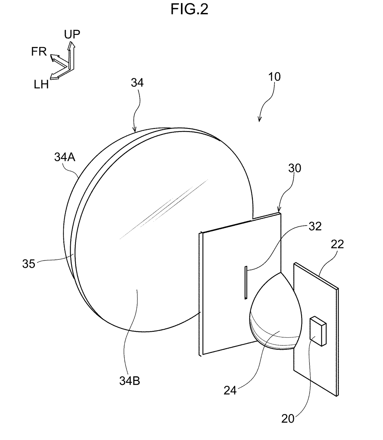
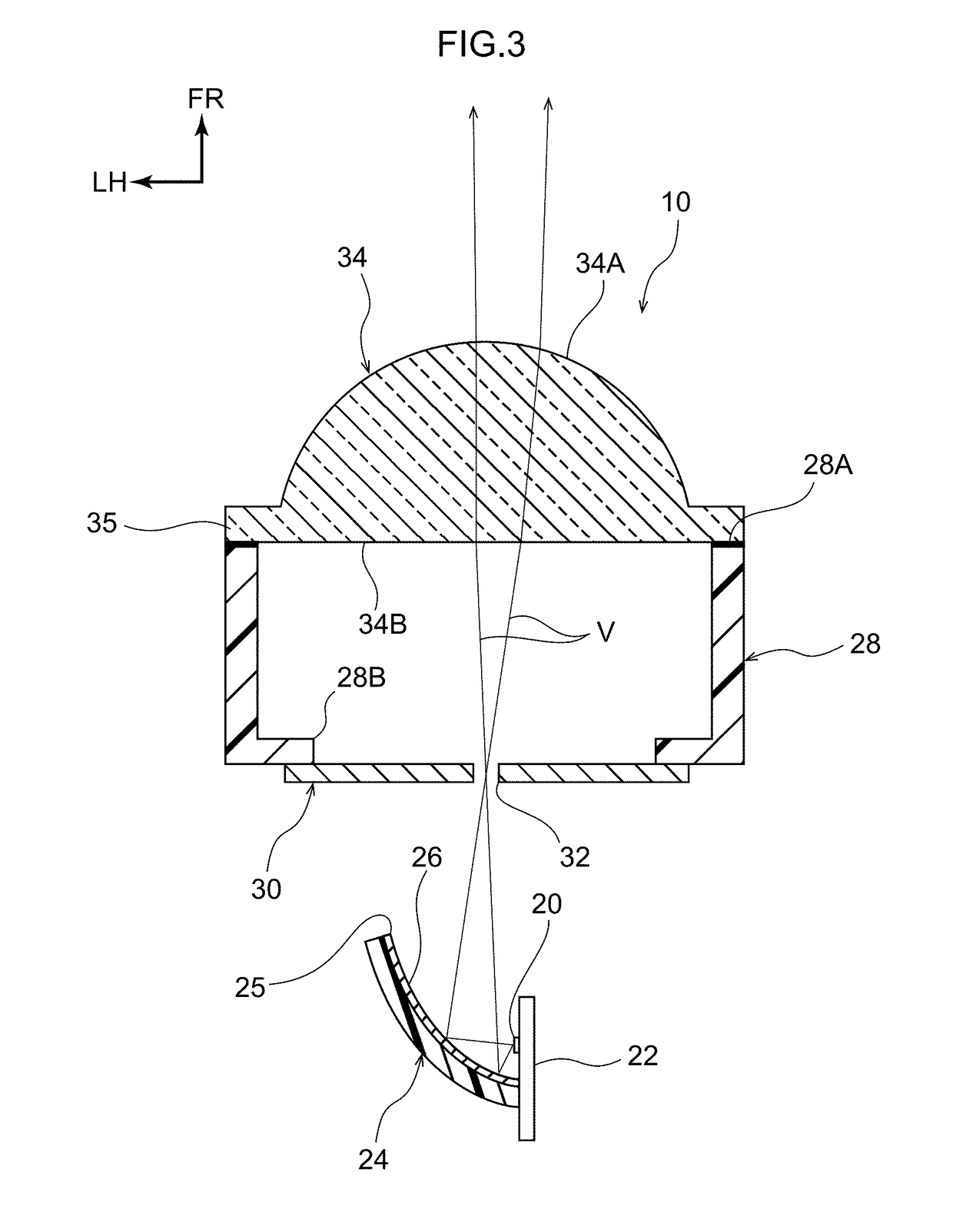
[0039]First, the lighting device for a vehicle 10 according to a first exemplary embodiment is described. As shown in FIG. 2 and FIG. 3, the lighting device for a vehicle 10 is equipped with a light source 20 and a reflecting member 24. The light source 20 illuminates light (visible light). The reflecting member 24 includes a reflecting surface 26 with a concave surface shape that reflects the light illuminated from the light source 20 and causes the light to converge.

[0040]The lighting device for a vehicle 10 is also equipped with a shading member 30 and a projecting lens 34. The shading member 30 includes an aperture portion 32, at which the light reflected and converged by the reflecting surface 26 is incident. The projecting lens 34 emits light that has passed through the aperture portion 32 of the shading member 30 and is incident on the projecting lens 34 toward a target (for example, a pedestrian walking at a roadside, a bicycle running at a roadside or the like that is at ri...

second exemplary embodiment

[0056]Now, the lighting device for a vehicle 10 according to a second exemplary embodiment is described. Portions that are the same as in the above-described first exemplary embodiment are assigned the same reference numerals and, as appropriate, are not described in detail.

[0057]As shown in FIG. 6A, FIG. 6B and FIG. 7, in the lighting device for a vehicle 10 according to the second exemplary embodiment, the shading member 30 and the reflecting member 24 are both formed integrally with a holder in a substantially tubular shape that has the optical axis direction in the front-and-rear direction. A mold 60 in which the holder 28 is injection-molded is shown in FIG. 9. As shown in FIG. 9, the mold 60 is structured by a fixed die 62, a movable die 64 and a slide 66.

[0058]As shown in FIG. 7, the projecting lens 34 is constituted by a plural number (two in this exemplary embodiment) of focusing lenses 36 and 38 that are arrayed in the optical axis direction and differ from one another in ...

third exemplary embodiment

[0080]Finally, the lighting device for a vehicle 10 according to a third exemplary embodiment is described. Portions that are the same as in the above-described first exemplary embodiment and second exemplary embodiment are assigned the same reference numerals and, as appropriate, are not described in detail (including operations that are the same).

[0081]As shown in FIG. 11, the third exemplary embodiment differs from the second exemplary embodiment described above only in that the concave surface shape of the reflecting mirror 25 (the reflecting surface 26) provided at the reflecting member 24 is a freeform curved surface. The meaning of the term “freeform curved surface” as used here is intended to exclude curved surfaces that may be represented by simple expressions, such as the surface of a sphere, and to include curved surfaces expressed by higher-order expressions applied in 3D graphics, which represent curved surfaces that cannot be expressed by simple expressions.

[0082]When ...


PUM


Abstract

A lighting device for a vehicle includes a light source that illuminates light, a reflecting surface, a shading member, and a projecting lens. The reflecting surface reflects the light illuminated from the light source and causes the light to converge. The shading member includes an aperture portion at which the light reflected and caused to converge by the reflecting surface is incident. Light that has passed through the aperture portion of the shading member is incident on the projecting lens, and the projecting lens emits the light toward a target.

Description

CROSS-REFERENCE TO RELATED APPLICATION[0001]This application is based on and claims priority under 35 USC 119 from Japanese Patent Application No. 2017-169878 filed on Sep. 4, 2017, the disclosure of which is incorporated by reference herein.TECHNICAL FIELD[0002]The present disclosure relates to a lighting device for a vehicle.RELATED ART[0003]Heretofore, a front lighting device for a vehicle has been proposed (for example, see Japanese Patent Application Laid-Open (JP-A) No. 2009-220631 (Patent Reference 1)) in which an illumination region of light illuminated from a light source is controlled by altering the position of a shading member such that the light is illuminated at a pedestrian walking at a roadside.[0004]However, with a configuration in which an illumination region of light illuminated from a light source is controlled by altering the position of a shading member, it is difficult to converge the light on an aperture portion of the shading member, and losses of light caus...

Claims


Application Information

Patent Timeline
Patent Type & Authority Applications(United States)
IPC IPC(8): F21S41/32F21S41/43F21S41/25
CPCF21S41/321F21S41/43F21S41/25B60Q1/02F21S41/365F21Y2115/10F21V7/04F21V14/06F21V33/0052F21W2102/13B60Q1/18B60Q2300/45F21S41/148F21S41/255F21S41/657
Inventor MOURI, FUMIHIKOKITAZONO, TAKUYAMYOJIN, NORIKATSU
Owner TOYOTA JIDOSHA KK
Why Eureka
Try Eureka