Stabilized gold wire brush for sliprings

a gold wire brush and slipring technology, applied in current collectors, electrical devices, rotary current collectors, etc., can solve the problems of affecting signal quality, affecting the signal quality, and affecting the stability of the brush, so as to reduce the impact of the vibration and/or oscillation of the brush, the effect of attenuating or reducing the effect of the vibration and/or oscillation

Active Publication Date: 2019-03-07
SCHLEIFRING GMBH
View PDF0 Cites 3 Cited by
  • Summary
  • Abstract
  • Description
  • Claims
  • Application Information

AI Technical Summary

Benefits of technology

[0021]The embodiments disclosed herein have the advantage, that vibrations and / or oscillations of the brush can be attenuated or reduced significantly. The stabilizer does not weaken the brush, nor does it change the spring properties which results in an unchanged contact force to a sliding track. There are no additional forces from external supports. The linear guidance by a V-groove in a sliding track is not affected, as there are no side forces to the brush. Also, the insulation properties remain unchanged. The new brush is fully compatible to previous brushes and can replace previous brushes without further modification of the slipring system.

Problems solved by technology

Due to external interference or by changes in friction, interfering movements of the brush other than the rotational movement or oscillations of the brush may occur.
Such interfering movements may cause contact noise and / or contact interruptions, adversely affecting signal quality.
In applications with an inductive load, electrical arcing may occur during such interruptions, which leads to significant corrosion and wear of the brush and the sliding track.
At lower values still melting can occur with subsequent damage and wear.
The drawback is the complex design having multiple thin wires held by a ferrule, which is expensive and difficult to manufacture.

Method used


Image

  • Stabilized gold wire brush for sliprings
  • Stabilized gold wire brush for sliprings
  • Stabilized gold wire brush for sliprings

Examples


first embodiment

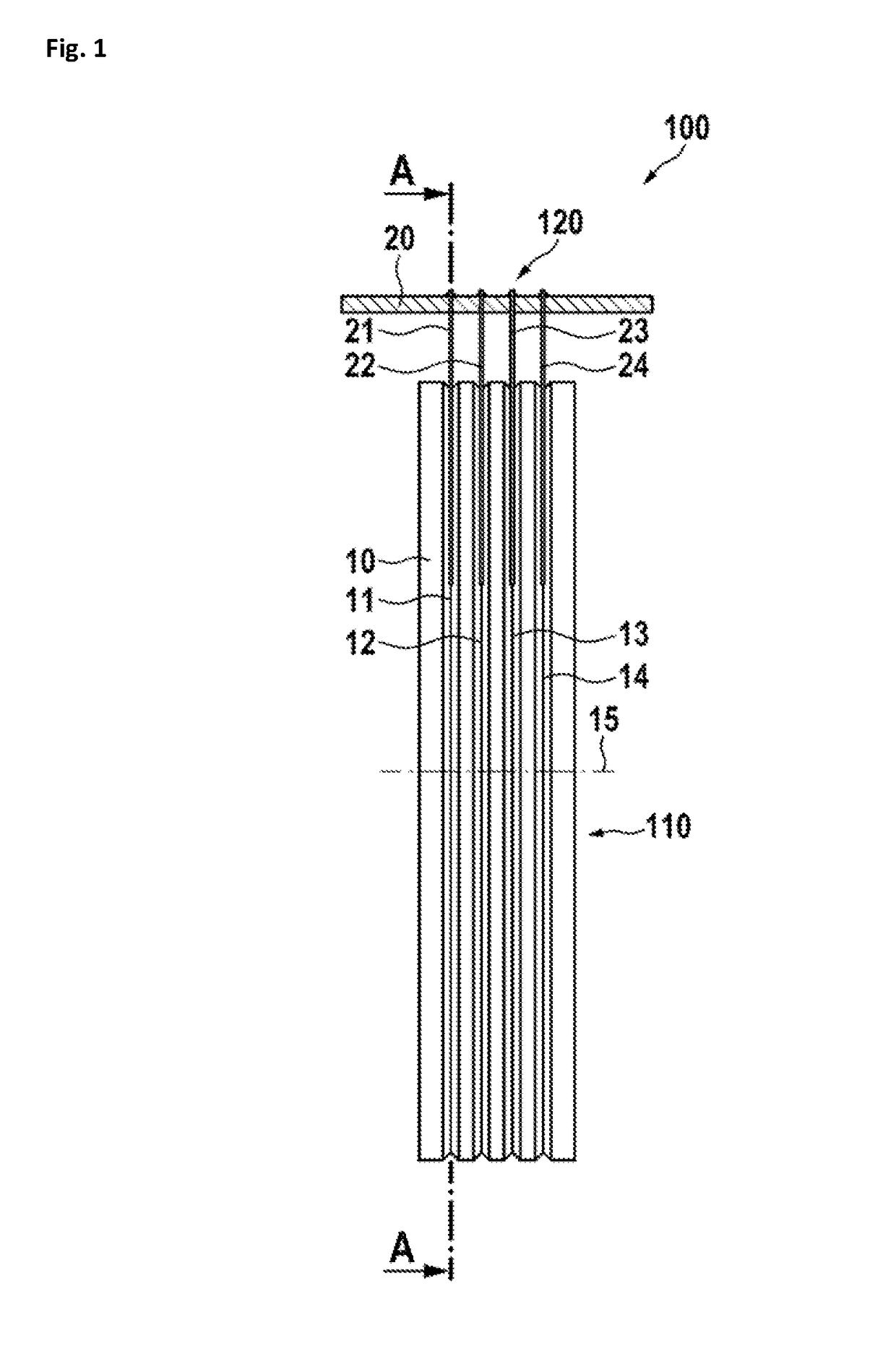
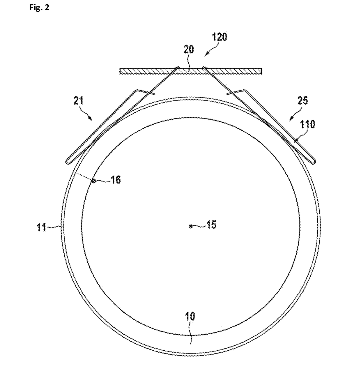
[0039]In FIG. 2, a sectional view of the first embodiment is shown in a plane cut through lines A-A in FIG. 1. It is preferred, if the slip-ring module have a free bore, for example a bore dimensioned to carry cable(s). A connector 16 is shown, which may be a soldering point or a soldering pin or a soldering connector employed to form electrical contact with the first sliding track 11. In practice, a connecting cable may be soldered to this connector 16. Preferably, the other sliding tracks also have respectively-corresponding connectors formed to contact these sliding tracks from the inner side of the insulating body (such as insulating body 10 as shown). In the embodiment of FIG. 2, the first sliding brush 21 and the fifth sliding brush 25 (corresponding to the first sliding brush 21 and disposed on the other side from the brush 21 with respect to a plane that contains the axis 15 and traverses the carrier 20) are in contact with the first sliding track 11.

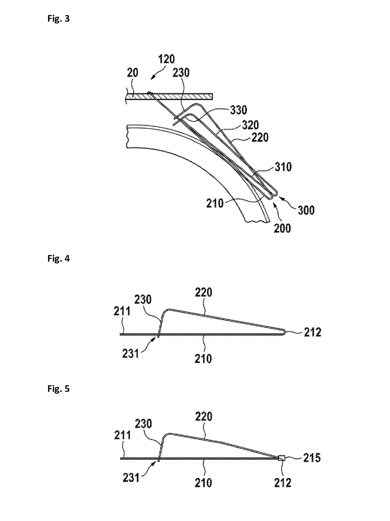
[0040]In FIG. 3, a parti...

embodiment 400

[0047]In FIG. 9, a sectional view of the embodiment 400 is shown in a plane cut through the center of the sliding track on the left in FIG. 8 (a plane that is perpendicular to the rotation axis 15). It is preferred, if the slip-ring module have a free bore, for example a bore dimensioned to carry cable(s). In the view of FIG. 9, a connector 16 is shown, which may be configured as a soldering point or a soldering pin or a soldering connector, which electrically contacts the first sliding track 411. A connecting cable may be soldered to this connector. Preferably, the other sliding tracks also have corresponding connectors to contact the sliding tracks from the inner side of the insulating body 410. In this embodiment, the first sliding brush 421 and the third sliding brush 425 (corresponding to the brush 421 and disposed on the other side of the track with respect to the plane that contains the axis 15 and that traverses the block 42) contact the same first sliding track 411.

[0048]In...


PUM


Abstract

A wire brush for a slipring includes a contact section, from which a stabilizer arm is extending backwards towards the brush block of the slipring. The stabilizer arm holds a friction section, which is in friction contact with the contact section at a friction contact area. Such contact, in operation, generates internal friction within the brush when the brush is moved and, therefore, suppresses oscillations of the brush.

Description

CROSS-REFERENCE TO RELATED APPLICATIONS[0001]This application claims priority to pending European Application No. 17189622.8 filed on Sep. 6, 2017, the disclosure of which is incorporated by reference herein.BACKGROUND1. Field of the Invention[0002]The invention relates to Slip-rings and brushes for Slip-Rings for transmission of electrical signals between rotating parts. Specifically, it relates to a stabilized gold wire brush which attenuates mechanical oscillations.2. Description of Relevant Art[0003]Electrical slip rings are used to transfer electrical power and / or signals between a rotating and a stationary part. Such devices are used in different applications, like wind energy plants or computer tomography scanners. There are also sever-al military and aerospace applications.[0004]It is common to all of these applications, that a high lifetime and a low contact resistance as well as a low contact noise are required. Furthermore, in specific applications like a CT scanner, cent...

Claims


Application Information

Patent Timeline
Patent Type & Authority Applications(United States)
IPC IPC(8): H01R39/64H01R39/24H01R39/02
CPCH01R39/64H01R39/24H01R39/025H01R39/46H01R39/18H01R39/39H01R39/36
Inventor GEYER, ROBERT
Owner SCHLEIFRING GMBH
Why Eureka
Try Eureka