Radiating integrated antenna unit and mutli-array antenna of same

a technology of integrated antennas and antennas, applied in the direction of polarised antenna unit combinations, particular array feeding systems, radiating element structural forms, etc., can solve the problems of limited capacity lift at macro sites and uplink coverage& capacity, difficulty in acquiring new, etc., to improve the complexity of traditional band-pass design and improve inter-port isolation

Active Publication Date: 2019-03-14
TONGYU COMM INC
View PDF3 Cites 4 Cited by
  • Summary
  • Abstract
  • Description
  • Claims
  • Application Information

AI Technical Summary

Benefits of technology

The integrated antenna unit described in this patent has two dual-polarized radiating elements connected to a reflecting board and a lid of two-band pass filters. Each band-pass filter is directly connected to a two-way power splitter, which connects the same polarization from the two radiating elements. This design has advantages such as improved inter-port isolation, no need for low-pass filtering, and reduced complexity and cost. Additionally, two walls running parallel to the filter edges support a cavity of the filters and serve as reflecting walls to control the 3 dB azimuth beam generated by the radiating elements.

Problems solved by technology

The technical problem addressed in this patent text is the challenges faced by regular antenna systems in terms of high-rise building coverage, capacity lift, and in-building capacity growth. These challenges are due to limited directive antennas and the difficulty in efficiently directing narrow beams at desired directions while nulling interferers. The text also highlights the limitations of traditional massive MIMO antennas, such as costly development and integration resources, weight, size, and integration flexibility issues. The ultimate goal of the patent text is to provide a solution to these challenges and limitations by introducing a new technology for efficient and flexible beam forming in higher frequency and hardware progress.

Method used


Image

  • Radiating integrated antenna unit and mutli-array antenna of same
  • Radiating integrated antenna unit and mutli-array antenna of same
  • Radiating integrated antenna unit and mutli-array antenna of same

Examples


Embodiment Construction

Best Mode

[0041]The physical embodiments adopted in the present invention will be presented by the following depicted embodiments and accompanying drawings for further explanations.

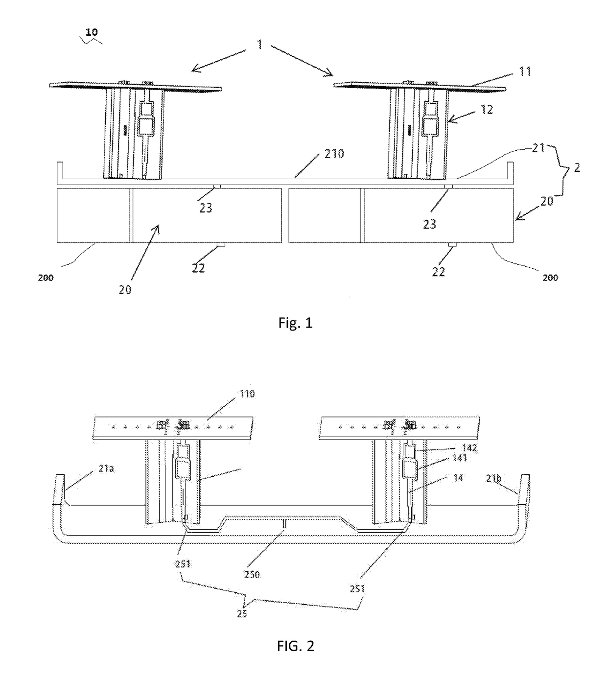
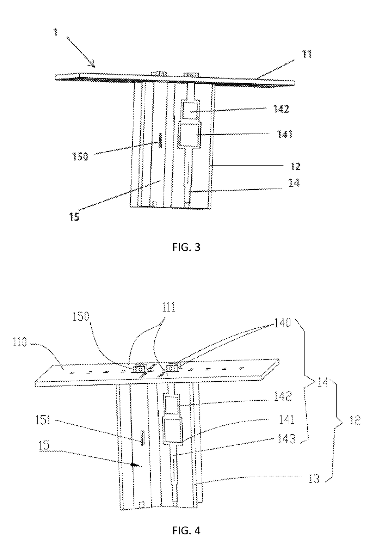
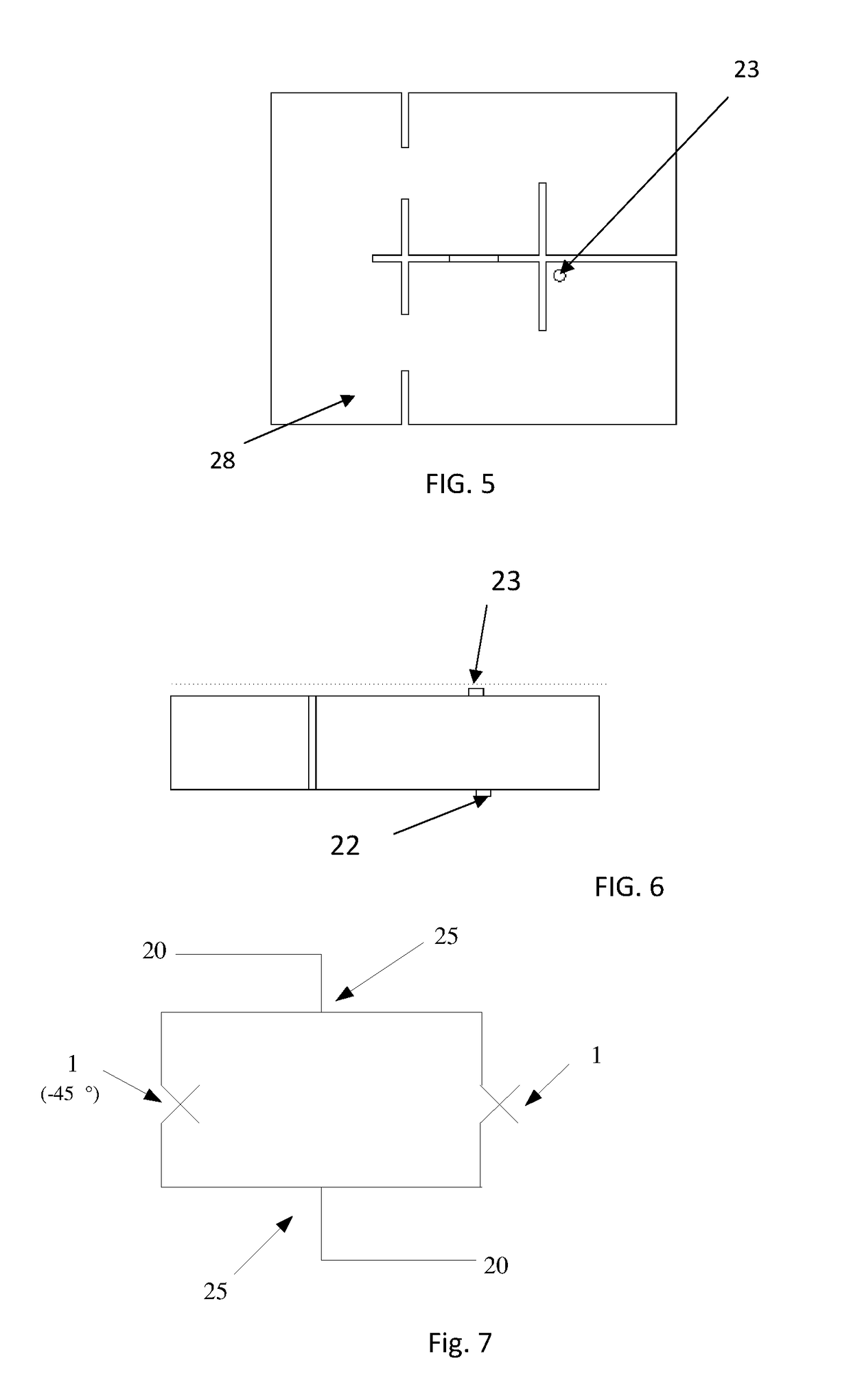
[0042]Referring to FIGS. 1-6, a radiating integrated antenna unit 10 comprises two radiating elements 1, and two band-pass filters 20 and a PCB 21 integrated together to form an integrated filtering device 2 supported under both radiating elements 1. The integrated filtering device 2 is constructed by two band-pass filters 20 and the PCB 21 of the integrated antenna unit 10. The PCB 21 serving as the filter lip is covered on both top ends of the two band-pass filters 20 and forms a reflector of both the radiating elements 1, thus a top surface 210 of the PCB 21 accordingly is a reflecting surface for both the radiating elements 1. Both the radiating elements 1 extend upwards from the top surface 210 of the PCB 21.

[0043]Accordingly, the PCB, the filter lid and the reflector may use the same reference number...


PUM


Abstract

An integrated antenna unit where two dual-polarized radiating elements are connected on a PCB serving reflecting board as well as a filter lid of two-band pass filters. Each of two band-pass filter is connected directly to a two-way power splitter serving connection of same polarization from the two radiating elements. Two walls running parallel are extending at the band-pass filter edges to support the cavity of the filters and at same time serving as reflecting walls enabling to control the 3 dB azimuth beam generated by the radiating elements. Next, a multi-array antenna by collocating multiple arrays of the integrated antenna units.

Description


Claims


Application Information

Patent Timeline
Owner TONGYU COMM INC
Why Eureka
Try Eureka