
Method for controlling the thickness of a continuous elongated element made of elastomeric material in a process for building tyres

a technology of elastomeric material and elongated elements, which is applied in the direction of tyres, domestic applications, other domestic articles, etc., can solve the problems of not being able to correctly manage elastomeric materials, not being able to treat and transport all types of elastomeric materials, etc., to achieve a strong and automatic drawling effect, reduce the formation of folds, and facilitate the effect of stretching

Active Publication Date: 2019-03-28
PIRELLI TYRE SPA
View PDF0 Cites 0 Cited by
  • Summary
  • Abstract
  • Description
  • Claims
  • Application Information

AI Technical Summary

Benefits of technology

The solution enables the production of tires with uniform thickness and radial symmetry, effectively managing adhesive and viscous elastomeric materials, reducing production waste, and preventing breakage by subdividing the stretching process, thus enhancing the quality and performance of the tires.

Problems solved by technology

The Applicant has observed that in devices such as those described in WO 2008 / 053278 or in WTO 2009 / 130727, the elements interposed between the extruder and the forming support are not suitable for treating and transporting all types of elastomeric material.
For example, the Applicant has verified that an assembly device like that described in WO 2008 / 053278 does not allow correctly managing elastomeric materials that are particularly adhesive, since the continuous elongated element formed by them tends to remain stuck to the lower roller of the calender, until it is wound thereon and causes the blocking thereof.

Method used


Image

  • Method for controlling the thickness of a continuous elongated element made of elastomeric material in a process for building tyres
  • Method for controlling the thickness of a continuous elongated element made of elastomeric material in a process for building tyres
  • Method for controlling the thickness of a continuous elongated element made of elastomeric material in a process for building tyres

Examples


Embodiment Construction

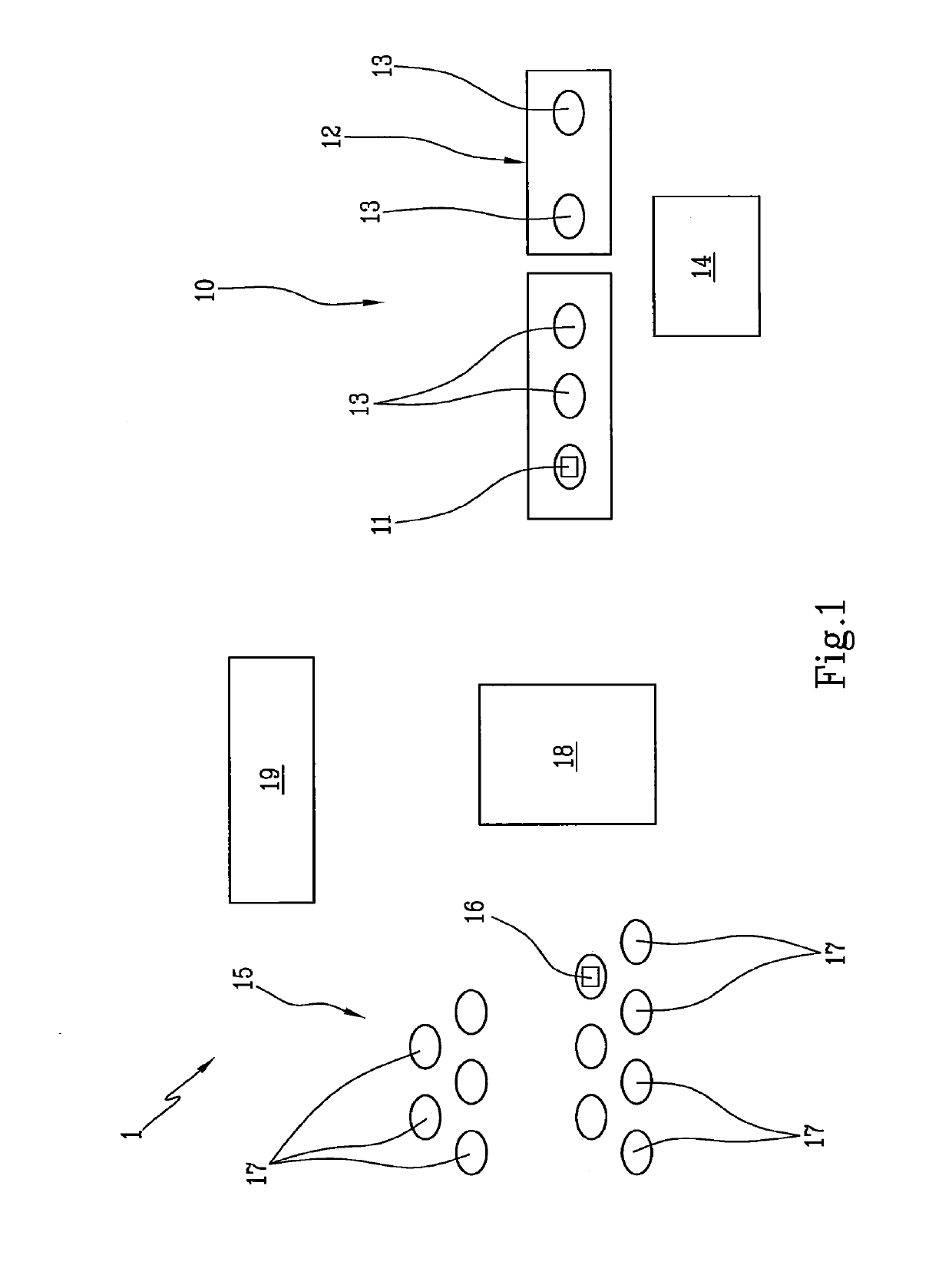
[0095]With reference to the abovementioned figures, with 1 a plant is indicated in its entirety for the building of tyres 2 in accordance with the present invention.

[0096]The plant 1 is set to obtain tyres 2 (FIG. 4) essentially comprising at least one carcass ply 3 preferably internally coated with a layer of impermeable elastomeric material or so-called liner 4, two so-called “beads”5 integrating respective annular anchoring structures 6 comprising respective bead cores 6a possibly associated with elastomeric fillers 6b and engaged with the circumferential edges of the carcass ply 3, a belt structure 7 applied in radially outer position to the carcass ply 3, a tread band 8 applied in radially outer position to the belt structure 7, in a so-called crown area of the tyre 2, and two sidewalls 9 applied in laterally opposite positions on the carcass ply 3, each at a lateral area of the tyre 2, being extended from the corresponding bead 5 to the corresponding lateral edge of the tread ...


PUM

PropertyMeasurementUnit
distanceaaaaaaaaaa
distanceaaaaaaaaaa
temperatureaaaaaaaaaa

Abstract

A method for controlling the thickness of a continuous elongated element made of elastomeric material, applied according to coils wound on a forming support, includes: advancing a head end of the continuous elongated element toward the forming support; subjecting, during the advancement, the continuous elongated element to a first stretching with a first stretch coefficient before applying on the forming support; and subjecting, during the advancement, the continuous elongated element to a second stretching with a second stretch coefficient during the application on the forming support. During the first stretching, a span of the continuous elongated element adjacent to the head end is stretched with a supplementary stretch coefficient greater than the first stretch coefficient, in a manner so as to confer, also to the span adjacent to the head end, a stretch and a section similar or substantially equivalent to those of the rest of the continuous elongated element.

Description

CROSS REFERENCE TO RELATED APPLICATIONS[0001]This application is a Divisional Application of U.S. patent application Ser. No. 14 / 433,268, filed Apr. 2, 2015, which is a National Phase Application based on PCT / IB2013 / 058999, filed Sep. 30, 2013, which claims the priority of Italian Patent Application No. MI2012A001695, filed Oct. 9, 2012, and the benefit of U.S. Provisional Application No. 61 / 715,556, filed Oct. 18, 2012, the content of each application being incorporated herein by reference in its entirety.BACKGROUND OF THE INVENTIONField of the Invention[0002]The present invention regards a method for controlling the thickness of a continuous elongated element made of elastomeric material in a process for building tyres for vehicle wheels.Description of the Related Art[0003]A tyre for vehicle wheels generally comprises a carcass structure comprising at least one carcass ply having respectively opposite terminal flaps engaged with respective annular anchoring structures, normally te...

Claims


Application Information

Patent Timeline
Patent Type & Authority Applications(United States)
IPC IPC(8): B29D30/16B29D30/30B29C47/00B29C47/34B29C43/48B29C48/03B29C48/07B29C48/355B29C48/37B29C48/92B29D30/60B29L30/00
CPCB29C2043/483B29C2948/92904B29C43/48B29C2043/486B29D30/30B29L2030/00B29D30/60B29C48/03B29C48/0011B29C48/355B29C48/07B29C48/37B29C48/92B29C2948/92076B29C2948/92438B29C2948/92647B29C2948/92704B29C2948/92885B29C2948/92895B29D30/16
Inventor FABBRETTI, MARCOCREPALDI, ANDREAAMURRI, CESARE EMANUELEMARCHINI, MAURIZIO
Owner PIRELLI TYRE SPA
Features
  • Generate Ideas
  • Intellectual Property
  • Life Sciences
  • Materials
  • Tech Scout
  • Unparalleled Data Quality
  • Higher Quality Content
  • 60% Fewer Hallucinations
Learn More