
Planter with high speed seed delivery apparatus

a planter and high-speed technology, applied in the field of agricultural planters with seed delivery apparatuses, can solve the problems of delay or non-vertical fall of seeds, affecting the seed spacing of planters, and additional problems

Active Publication Date: 2019-04-04
KINZE MFG INC
View PDF0 Cites 30 Cited by
  • Summary
  • Abstract
  • Description
  • Claims
  • Application Information

AI Technical Summary

Benefits of technology

This patented technology describes a device called a row units used with an aircraft's plant-propelling system (EP) or airplanes equipped with this type of equipment. These devices are designed specifically for delivering fertilizers onto crops during their growth cycle by moving them through soil layers underground without damaging nearby structures like roads. To ensure proper functioning, these rows can rotate around a central hub connected to two wheels. One end faces downwards at right angles to the center line while the opposite ends up against gravity when they move vertically back over top. Another part of the row also contains holes arranged regularly across its surface. When there is no flow of water inside, some roots extend beyond those holes but still fit tightly together. There is also included a tray made of rubber covered with tiny openings containing small balls. By turning the roller clockwise, certain ones of the ball hold the remaining rootlets attached to the outside of the tire.

Problems solved by technology

The technical problem addressed in this patent text is the inconsistent spacing of seeds in an agricultural planting implement caused by interruptions or forces acting on the seeds, which can result in poor crop yield. The patent aims to provide an improved seed delivery apparatus to ensure more consistent seed spacing and increased yield.

Method used


Image

  • Planter with high speed seed delivery apparatus
  • Planter with high speed seed delivery apparatus
  • Planter with high speed seed delivery apparatus

Examples


Embodiment Construction

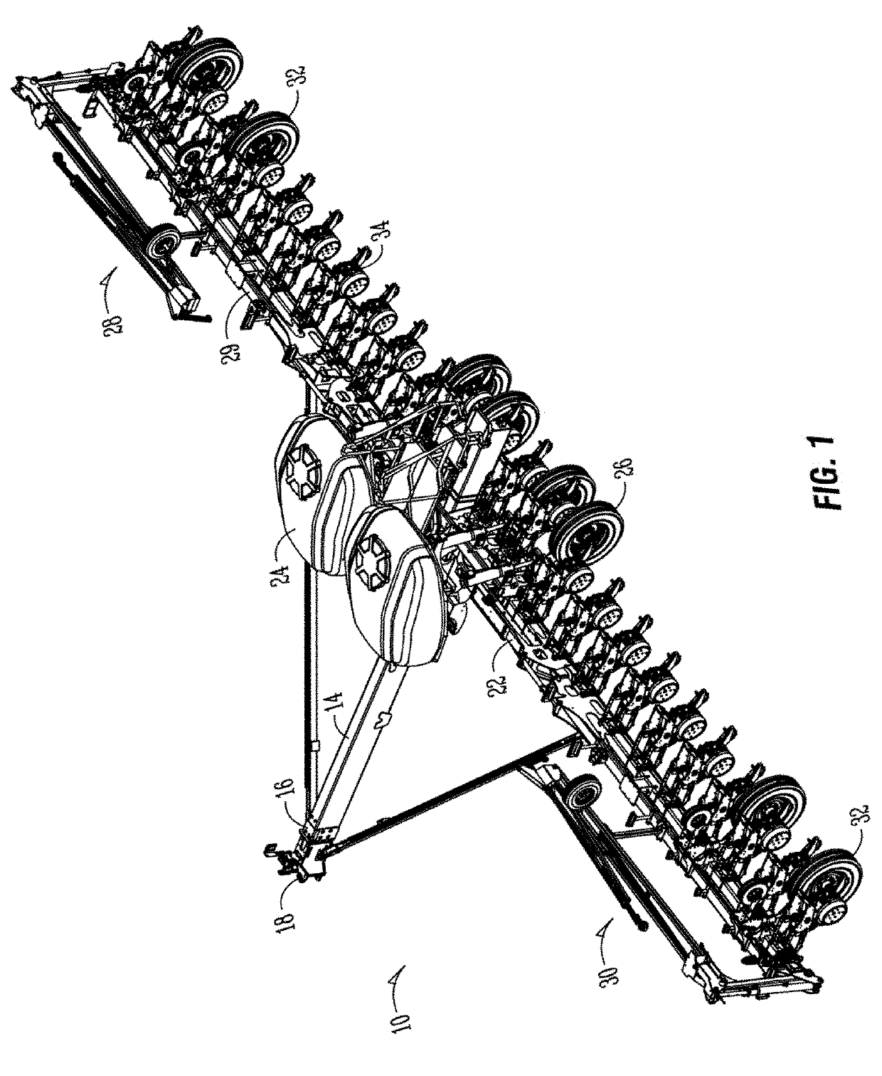
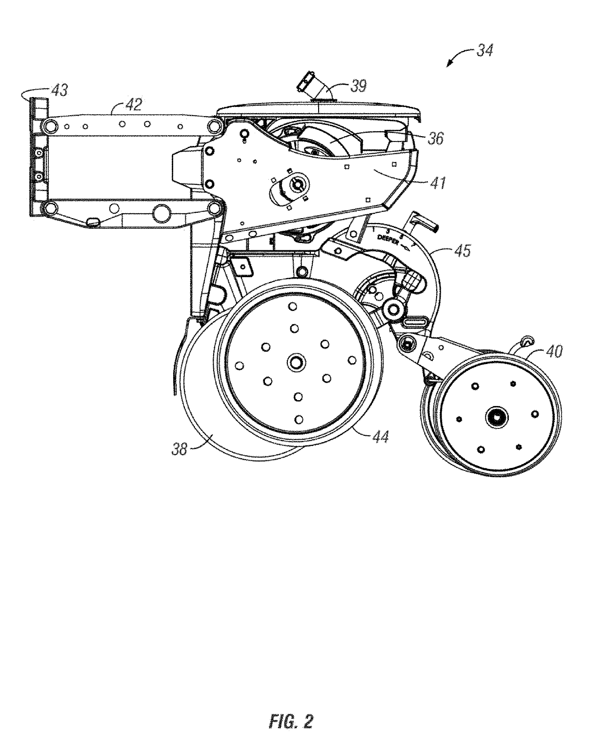
[0064]FIG. 1 shows an agricultural implement 10, in this case, an agricultural planter. The planter 10 is usually attached to and pulled by a tractor. However, it should be appreciated that other equipment and / or vehicles may move the implement 10. For purposes of the present disclosure, the implement 10 will be referred to as a planter.

[0065]The planter 10 includes a tongue 14 having a first end 16 and an opposite second end (not shown). The tongue 14 includes a hitch 18 at the first end 16, with the hitch 18 being connected to the tractor. At the opposite end of the tongue 14 is a central tool bar 22. The tongue 14 may be a telescoping tongue with components capable of being inserted into one another such that the implement 10 is a front folding style implement. However, the present invention is not to be limited to such front folding style implements and is to include any such implement for use in the agricultural industry.

[0066]As shown in FIG. 1, central hoppers 24 are position...


PUM


Abstract

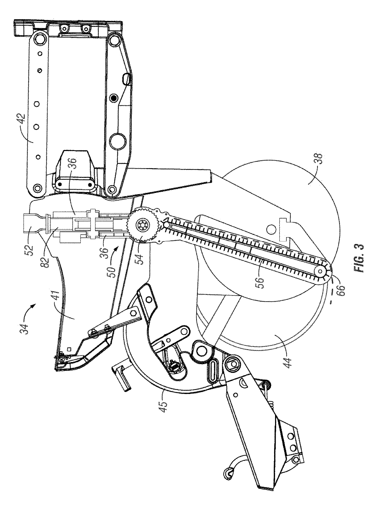
An agricultural planting implement includes a number of row units. The row units include one or more seed meters for receiving, singulating, and dispensing seed to the ground such that preferred spacing of subsequent seed is attained. A seed meter provides seeds one at time to a seed carrier, such as a brush wheel. The brush wheel may move the seeds one at a time to a seed conveyor by directly moving seeds along a curved portion of a seed disc in the seed meter. The seed conveyor may be a flighted belt, and the velocity of the seeds when transferred from the seed carrier may match the velocity of the flighted belt. The seed conveyor conveys the seeds to a position near the bottom of a furrow, and ejects the seeds with little or no horizontal velocity relative to the bottom of the furrow.

Description


Claims


Application Information

Patent Timeline
Owner KINZE MFG INC
Learn More