Eureka AIR delivers breakthrough ideas for toughest innovation challenges, trusted by R&D personnel around the world.

Liquid Jetting Apparatus Including Purge Mechanism

Active Publication Date: 2019-04-04
BROTHER KOGYO KK
View PDF2 Cites 1 Cited by
  • Summary
  • Abstract
  • Description
  • Claims
  • Application Information

AI Technical Summary

Benefits of technology

The patent text explains a method for preventing ink from thickening in a printer nozzle during a purge process. By performing a purge after a jetting instruction, the ink is discharged from the nozzle to prevent the ink from becoming too viscous. This method ensures that the ink is always ready for printing, improving the reliability of the printing process.

Problems solved by technology

As a result, there is such a fear that the purge might be performed unnecessarily and the ink might be discharged in vain or wastefully.

Method used


Image

  • Liquid Jetting Apparatus Including Purge Mechanism
  • Liquid Jetting Apparatus Including Purge Mechanism
  • Liquid Jetting Apparatus Including Purge Mechanism

Examples


Embodiment Construction

[0020]In the following, an embodiment of the present teaching will be explained, with reference to the drawings as appropriate.

[0021]

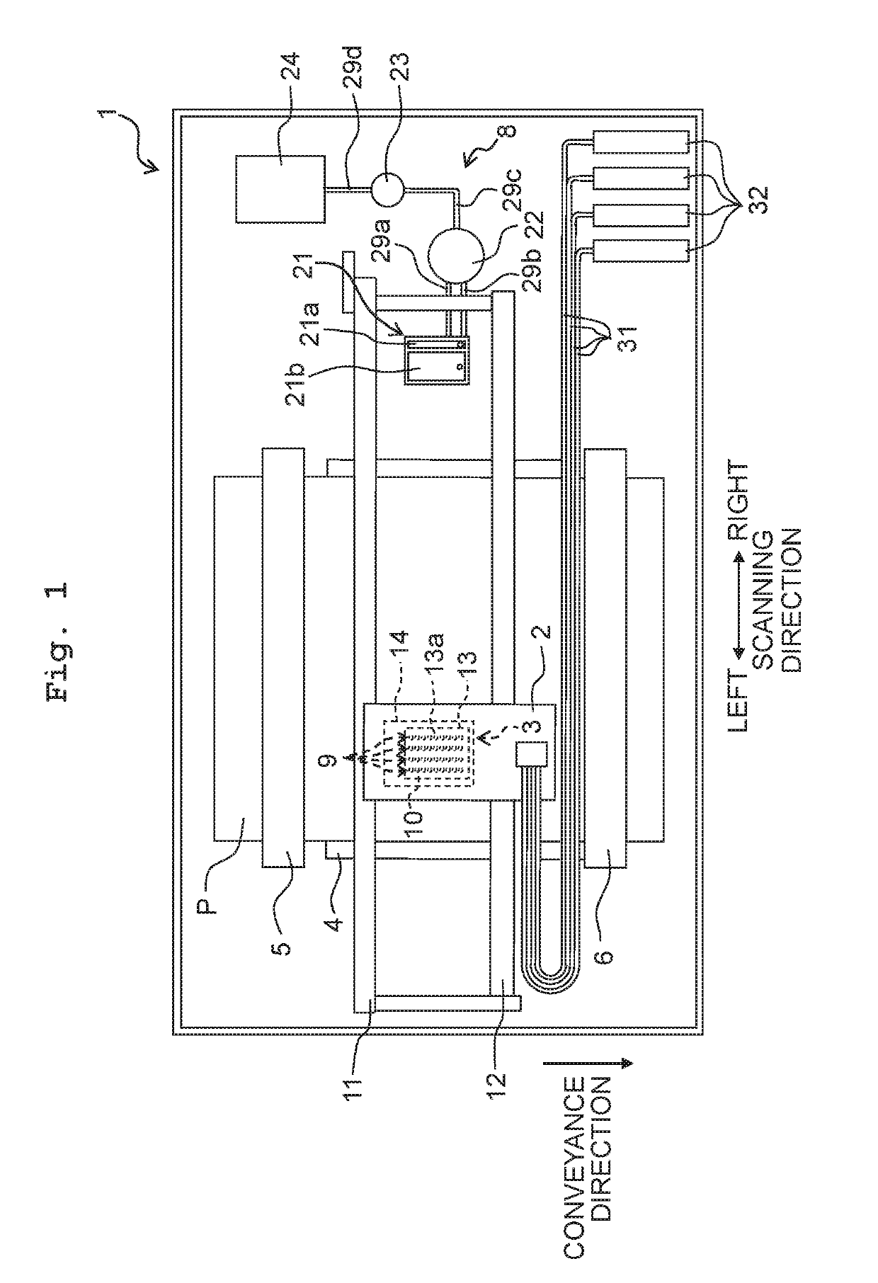
[0022]As depicted in FIG. 1, a printer 1 according to an embodiment of the present teaching (corresponding to a “liquid jetting apparatus” of the present teaching) is provided with a carriage 2, an ink-jet head 3 (corresponding to a “liquid jetting head” of the present teaching), a platen 4, conveyance rollers 5 and 6, a flushing foam 7, a maintenance unit 8, etc.

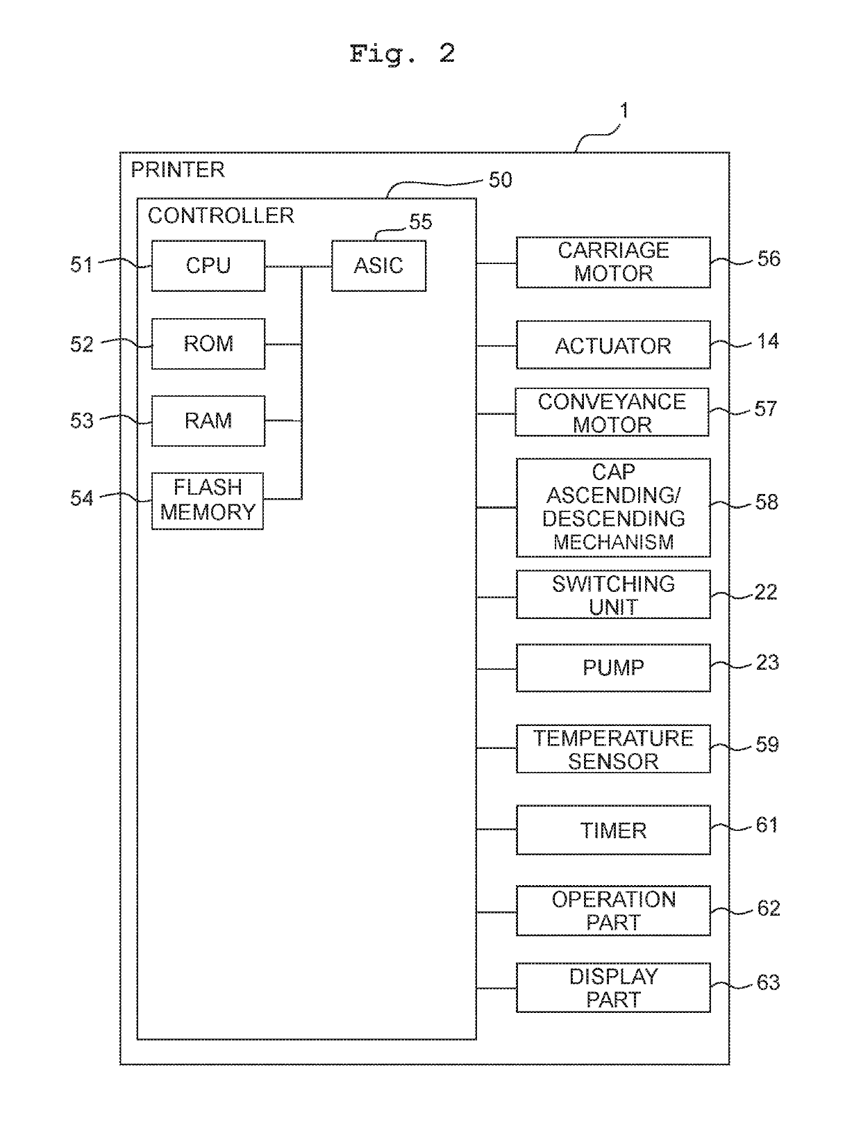
[0023]The carriage 2 is supported by two guide rails 11 and 12 extending in a scanning direction. Further, the carriage 2 is connected to a carriage motor 56 (see FIG. 2) via a non-illustrated belt, etc.; in a case that the carriage motor 56 is driven, the carriage 2 is thereby reciprocated in the scanning direction along the guide rails 11 and 12. Note that in the following explanation, the right and left sides in the scanning direction are defined as the right and left sides depicted in FIG....


PUM


Abstract

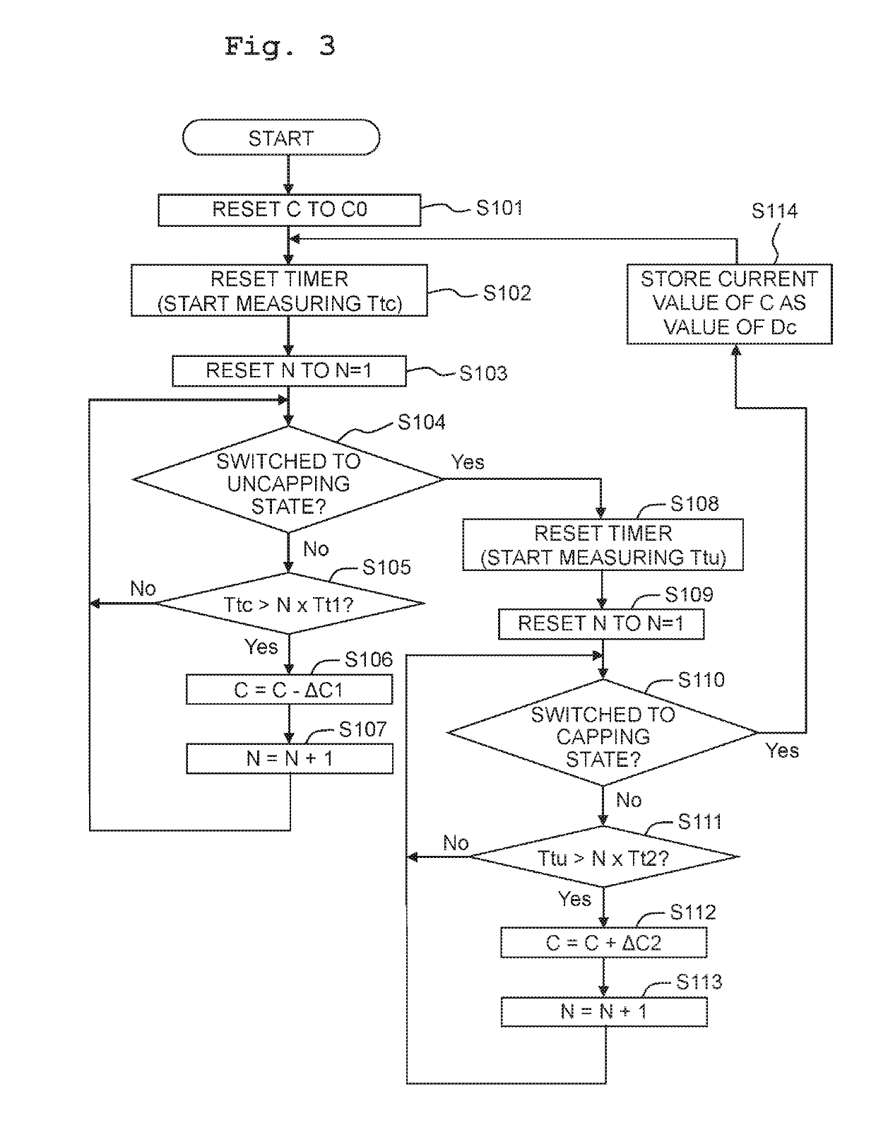
There is provided a liquid jetting apparatus including: a liquid jetting head; a cap; a switching mechanism configured to perform switching of a state of the cap between a capping state and an uncapping state; a timer; a purge mechanism; and a controller. The controller performs: calculating a value of a capping-time parameter; and measuring a capping time with the timer. In a case that a purge condition regarding the capping time and the value of the capping-time parameter is satisfied, the controller causes the purge mechanism to perform a purge, and then causes the liquid jetting head to perform a jetting operation.

Description

CROSS REFERENCE TO RELATED APPLICATION[0001]The present application claims priority from Japanese Patent Application No. 2017-189856 filed on Sep. 29, 2017, the disclosures of which are incorporated herein by reference in its entirety.BACKGROUNDField of the Invention[0002]The present disclosure relates to a liquid jetting apparatus which jets liquid from a nozzle.Description of the Related Art[0003]As an example of a liquid jetting apparatus which jets liquid from a nozzle, there is a publicly known printer which jets an ink from a nozzle so as to perform printing. In this publicly known printer, a purge is performed for causing the ink to be discharged (jetted) from the nozzle into a cap. Further, in the publicly known printer, the nozzle is covered by the cap in a stand-by state in which no printing is performed, thereby suppressing the increase in viscosity of the ink inside the nozzle.SUMMARY[0004]Here, even in a case that empty suction for discharging the ink from the cap is pe...

Claims


Application Information

Patent Timeline
IPC IPC(8): B41J2/165
CPCB41J2/16505B41J2/16508B41J2/16517B41J2/16526B41J2002/16573
Inventor IIDA, SHOTARO
Owner BROTHER KOGYO KK
Why Eureka
Eureka Blog
Learn More